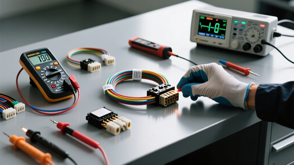
The Anatomy of an Auto Electrical Problem
Every automotive electrical problem fundamentally boils down to an anomaly in voltage, current, or resistance. Whether you are chasing a parasitic battery drain, diagnosing a high-resistance ground on a fuel pump circuit, or decoding a CAN bus communication fault, selecting the correct diagnostic instrument is the difference between a swift repair and hours of chasing ghost faults. Modern vehicles utilize multiplexed networks, pulse-width modulated (PWM) signals, and highly sensitive electronic control units (ECUs). Relying on outdated methods or the wrong tool can not only fail to identify the electrical problem but can also inadvertently damage sensitive microprocessors.
This guide compares the industry-standard diagnostic tools—Digital Multimeters (DMM), Automotive Oscilloscopes, and Circuit Tracers—and provides a selection matrix to help you match the right instrument to your specific wiring fault.
Diagnostic Tool Comparison Matrix
Before diving into specific repair scenarios, it is critical to understand the operational limits of your testing equipment. The table below outlines the primary tools used by professional automotive electricians.
| Tool Type | Impedance / Specification | Best Application | Primary Limitation |
|---|---|---|---|
| Automotive DMM (e.g., Fluke 88V) | 10 Megohm input impedance, True RMS, MIN/MAX recording | Voltage drop testing, resistance checks, parasitic draw (mV drop method) | Too slow to capture high-speed data bus faults or micro-second sensor glitches |
| Oscilloscope (e.g., PicoScope 4425A) | 12-bit resolution, 20 MHz bandwidth, up to 200V input | CAN bus differential signaling, CKP/CMP correlation, PWM injector analysis | Requires advanced waveform interpretation skills; higher initial cost |
| Incandescent Test Light | Low impedance (draws 250mA - 500mA) | Verifying high-current power and ground availability under load | Can blow delicate ECU driver circuits; useless for data bus or sensor diagnostics |
| Powered Circuit Tracer | Variable output, typically 6V-12V with short-circuit protection | Locating hidden shorts-to-ground, verifying continuity in long harness runs | Risk of back-feeding voltage into sensitive modules if not properly isolated |
Digital Multimeters (DMM): The Baseline for Voltage and Resistance
A high-quality automotive DMM is mandatory for any electrical problem involving static voltage or resistance. The Fluke 88V is the industry benchmark due to its built-in automotive features, including RPM inductive pickups, duty cycle measurement, and pulse width capabilities. Crucially, its 10 Megohm input impedance ensures that it will not load down delicate sensor reference voltage circuits (like a 5V throttle position sensor) while back-probing. When diagnosing an electrical problem related to voltage drop, the DMM's MIN/MAX function is invaluable for capturing intermittent voltage sags that occur only when a vehicle hits a bump.
Automotive Oscilloscopes: Capturing High-Speed Data
When an electrical problem involves communication networks or fast-acting sensors, a DMM is effectively blind. An automotive oscilloscope, such as the PicoScope 4425A, graphs voltage over time, allowing you to see the exact shape of a signal. For example, a failing Hall-effect camshaft position sensor may show a perfect 12V to 0V square wave on a multimeter, but a scope will reveal a rounded, degraded rising edge caused by internal magnetic interference or wiring capacitance. According to the Pico Technology Waveform Library, visualizing the physical waveform is the only definitive way to diagnose intermittent signal dropouts in crankshaft and camshaft correlation faults.
Real-World Diagnostic Scenarios and Tool Selection
Scenario 1: Parasitic Battery Drain (Key-Off Draw)
The Electrical Problem: The vehicle battery dies after sitting for 48 hours.
The Wrong Tool: Pulling fuses one by one while watching an ammeter in series with the battery terminal. This disrupts the vehicle's sleep cycle, causing modules to wake up and skewing the data.
The Right Tool: DMM set to Millivolts (mV).
The Procedure: Modern vehicles require the parasitic draw test to be performed without breaking the circuit. Using a DMM, measure the voltage drop across the blade of each standard ATO/ATC mini fuse. Every fuse acts as a low-value shunt resistor. By referencing the fuse resistance chart, you can calculate the exact current draw without waking the modules.
| Fuse Type & Rating | Approx. Resistance | mV Drop per 100mA Draw |
|---|---|---|
| Mini (ATM) 10A | 0.0075 Ω | 0.75 mV |
| Standard (ATO) 20A | 0.0045 Ω | 0.45 mV |
| Maxi 40A | 0.0022 Ω | 0.22 mV |
If you measure 2.25 mV across a 20A ATO fuse, the circuit is drawing exactly 500mA (2.25 / 0.0045 = 0.5A). As noted by Fluke Automotive, this non-intrusive mV drop method is the safest and most accurate way to isolate a parasitic electrical problem.
Scenario 2: Intermittent CAN Bus Communication Fault (U-Codes)
The Electrical Problem: The scan tool displays U0100 (Lost Communication with ECM) and the transmission enters limp mode.
The Wrong Tool: A standard DMM measuring static voltage on OBD2 DLC Pins 6 and 14.
The Right Tool: Automotive Oscilloscope with differential leads.
The Procedure: The Controller Area Network (CAN) utilizes a twisted pair of 20 AWG (0.5mm²) wires: CAN-High and CAN-Low. In a healthy state, CAN-H rests at 2.5V and spikes to 3.5V (Dominant), while CAN-L rests at 2.5V and drops to 1.5V. If there is an electrical problem like a short to ground, or a missing 120-ohm termination resistor, the differential signal will collapse. Connect the scope to DLC Pin 6 (CAN-H) and Pin 14 (CAN-L). If the waveform shows CAN-H and CAN-L tracking each other identically instead of mirroring, you have a short between the two wires. If the total resting voltage is skewed, you likely have a corroded splice or a failed termination resistor inside the ECM or ABS module. Always verify the parallel resistance of the CAN bus with a DMM; a healthy network must read exactly 60 ohms (two 120-ohm resistors in parallel).
Scenario 3: High-Resistance Ground on High-Current Circuits
The Electrical Problem: The starter motor cranks slowly, and the headlights dim severely during cranking.
The Wrong Tool: A test light (which only confirms the presence of voltage, not the volume of current available).
The Right Tool: DMM performing dynamic Voltage Drop Testing.
The Procedure: A high-current circuit utilizing 4 AWG SAE J1128 stranded copper wire should exhibit virtually no resistance. However, corrosion at the battery terminal or the engine block grounding point creates a bottleneck. Set your DMM to DC Volts. Place the red lead on the battery negative post and the black lead on the starter motor casing. Crank the engine. According to SAE diagnostic standards and general automotive electrical theory, the maximum allowable voltage drop on the ground side of a high-current starter circuit is 0.20V (200mV). If your DMM reads 0.85V, the electrical problem is severe galvanic corrosion or fretting at the ground lug, robbing the starter of necessary amperage. Clean the mating surfaces to bare metal and apply dielectric grease to prevent future oxidation.
Probe Selection and Connector Preservation
A common mistake when diagnosing an electrical problem is using thick, standard DMM probes to back-probe weather-pack connectors. Forcing a thick probe into a female terminal will spread the terminal tangs, leading to intermittent connection issues and fretting corrosion long after your test is complete. Always use the correct T-pin or back-probe size for the connector family.
| Connector Type | Terminal Width | Recommended Back-Probe | Common Automotive Application |
|---|---|---|---|
| TE Superseal 1.2 | 1.2mm | 0.5mm - 0.6mm T-Pin | Engine sensors, ABS wheel speed sensors |
| Molex MX150 | 1.5mm | 0.64mm T-Pin | ECU/PCM harnesses, transmission solenoids |
| Deutsch DT | 1.59mm (Size 16) | 0.8mm T-Pin or Piercing Probe | Heavy-duty truck harnesses, diesel injectors |
| Standard Weather-Pack | 2.8mm | 1.0mm T-Pin | Older GM/Ford lighting and accessory circuits |
Conclusion
Solving a complex automotive electrical problem requires more than just a parts cannon; it requires a systematic approach matched with the correct diagnostic instrument. Use a high-impedance DMM for static voltage, resistance, and non-intrusive parasitic draw testing. Deploy an automotive oscilloscope when the fault involves high-speed data networks, PWM signals, or micro-second sensor anomalies. Finally, respect the physical integrity of the wiring harness by utilizing proper back-probing techniques. By aligning your tool selection with the specific physics of the fault, you will diagnose electrical problems faster, safer, and with absolute certainty.