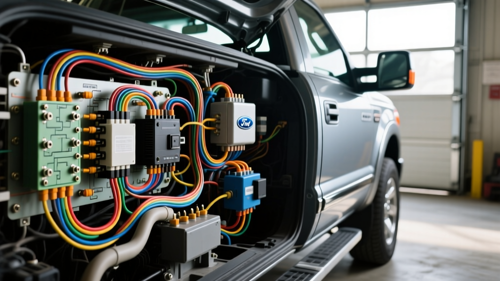
The Hidden Dangers of Automotive Electrical Diagnostics
When you encounter a complex wiring problem in car electrical systems, the difference between a successful repair and a catastrophic module failure often comes down to diagnostic discipline. Modern vehicles, particularly late-model trucks like the 2015-2020 Ford F-150, rely on high-speed Controller Area Network (HS-CAN) and Medium-Speed CAN (MS-CAN) multiplexed data buses. These networks operate on delicate voltage tolerances and low-current thresholds. Treating a modern data bus like a legacy 12-volt lighting circuit is a guaranteed way to destroy a Powertrain Control Module (PCM) or Body Control Module (BCM). This guide outlines the five most destructive mistakes technicians and DIYers make when chasing a communication or sensor wiring problem in car networks, complete with specific pinouts, wire gauges, and procedural corrections.
Mistake #1: Probing Data Lines with a Standard Incandescent Test Light
The most common cause of secondary module damage during electrical troubleshooting is using a standard 12V incandescent test light to check for power or ground on CAN bus circuits. A typical test light draws between 250mA and 500mA of current. CAN bus transceivers inside the PCM and BCM are designed to operate at extremely low current thresholds, typically peaking around 70mA to 120mA during dominant state transmission.
If you probe Pin 6 (CAN-H) or Pin 14 (CAN-L) on the OBD2 Data Link Connector (DLC) with a test light, you will instantly overload the transceiver, causing internal thermal failure. Furthermore, test lights cannot read the rapid digital square-wave signals of a CAN bus. To properly diagnose a wiring problem in car data networks, you must use a high-impedance Digital Multimeter (DMM) set to DC Volts, or ideally, an oscilloscope to view the differential signaling. A healthy HS-CAN bus will show CAN-H toggling between 2.5V (recessive) and 3.5V (dominant), while CAN-L toggles between 2.5V and 1.5V.
Mistake #2: Ignoring Voltage Drop on PCM Chassis Grounds
A frequent misdiagnosis of a wiring problem in car engine management systems involves replacing expensive sensors when the actual fault is a degraded chassis ground. On the Ford F-150, the PCM relies on heavy 10 AWG black wires terminating at ground points like G101 (left cylinder head) and G102 (right cylinder head). Over time, thermal cycling and exposure to road salt cause fretting corrosion at the ring terminal interfaces.
Do not rely on a simple continuity test; a DMM will read 0.0 ohms even if only one strand of a 10 AWG wire is intact, which is useless under load. Instead, perform a dynamic voltage drop test. Set your DMM to the DC millivolt (mV) scale. Place the red lead on the sensor's ground terminal (e.g., a TP sensor ground) and the black lead directly on the battery negative post. With the engine running and sensors active, the voltage drop across the ground circuit must not exceed 100mV (0.10V). A reading of 150mV or higher indicates excessive resistance, requiring you to remove the G101 ground bolt, clean the mating surface with a brass wire brush, and apply dielectric grease to prevent future oxidation.
Mistake #3: Piercing Wire Insulation for Backprobing
When trying to isolate a wiring problem in car harnesses, many technicians resort to piercing probes to bite through the wire insulation and make contact with the copper conductor. While this provides a quick reading, it introduces a fatal long-term flaw: copper oxidation, commonly known as "green death" or verdigris.
Automotive harnesses use thin-wall cross-linked polyethylene (XLPE) or PVC insulation. Piercing this insulation creates a microscopic breach. Capillary action wicks moisture directly into the copper strands. Within months, copper oxide forms, which is a semiconductor, not a conductor. This creates a high-resistance fault that will drive you crazy to diagnose later. Always backprobe connectors from the rear using properly sized T-pins or specialized backprobe pins that slip past the weather-pack seals without damaging the terminal. If you must splice into a wire for a temporary scope test, use a high-quality insulation displacement connector (IDC) designed specifically for automotive data lines, or carefully strip and solder-seal the repair afterward.
Mistake #4: Soldering Splices in High-Vibration Harnesses
While soldering is often considered the gold standard in household electronics, it is a major mistake when repairing a wiring problem in car engine bays or suspension harnesses. Solder wicks into the copper strands via capillary action, creating a rigid, inflexible section of wire. In high-vibration environments (like near the transmission bellhousing or wheel speed sensors), this rigid section creates a stress riser. The wire will inevitably fatigue and snap exactly at the edge of the solder joint.
The correct repair method for 18 AWG to 12 AWG automotive wires is a mechanical crimp using an open-barrel or closed-barrel terminal, followed by sealing. For inline splices, use a staggered Western Union mechanical twist, crimp it securely, and seal it with dual-wall, adhesive-lined heat shrink tubing (such as 3M EPS200). The inner layer of hot-melt adhesive melts and flows into the wire strands, creating a waterproof, strain-relieved seal that flexes with the harness without breaking.
Mistake #5: Forgetting the Battery Management System (BMS) Reset
When diagnosing a parasitic drain or a severe wiring problem in car charging systems, you often need to disconnect the battery. On modern vehicles equipped with Absorbent Glass Mat (AGM) batteries and a Battery Current Sensor (BCS) on the negative terminal, the vehicle's Battery Management System (BMS) tracks the exact state of charge and battery age.
If you replace a battery or leave it disconnected for an extended diagnostic period without performing a BMS reset via an OBD2 scan tool, the PCM will continue to charge the battery based on its old degradation profile. This leads to severe overcharging, boiling the AGM electrolyte, and ultimately destroying the new battery within months. Always execute the manufacturer-specific BMS reset procedure after any battery disconnect or replacement.
2018 Ford F-150 OBD2 DLC & HS-CAN Reference Chart
When tracking a communication wiring problem in car networks, referencing the exact pinout of the Data Link Connector is critical. The following table details the HS-CAN and power circuits at the 16-pin DLC, governed by the SAE J1962 Standard.
| DLC Pin | Circuit Designation | Wire Color (Typical) | AWG | Function / Notes |
|---|---|---|---|---|
| 4 | SBP-GND | Black | 18 | Chassis / Signal Ground |
| 5 | SBP-GND | Black | 18 | Signal Ground (PCM logic) |
| 6 | HS-CAN (+) | White/Blue | 18 | High-Speed CAN High (2.5V - 3.5V) |
| 14 | HS-CAN (-) | White | 18 | High-Speed CAN Low (1.5V - 2.5V) |
| 16 | SBP-BATT | Yellow/Green | 14 | Constant Battery Voltage (Fused) |
Note: Always verify total bus resistance between Pin 6 and Pin 14 with the battery disconnected. A healthy HS-CAN bus will read exactly 60 ohms, representing two 120-ohm terminating resistors in parallel.
Symptom-Cause-Fix Decision Tree for No-Comm Issues
Use this structured diagnostic tree when your scan tool fails to communicate with the PCM, a classic symptom of a severe wiring problem in car data networks.
- Symptom: Scan Tool displays "Link Error" or "No Communication with PCM".
- Step 1: Check DLC Pin 16 for 12V and Pin 4/5 for < 0.5 ohms to battery negative.
- Result A (Power/Ground Missing): Check Central Junction Box (CJB) fuses (e.g., F22, F33) and ground splices.
- Result B (Power/Ground OK): Proceed to Step 2.
- Step 2: Measure resistance between DLC Pin 6 and Pin 14 (Battery Disconnected).
- Result A (120 ohms): One terminating resistor is missing or an open circuit exists in the CAN-H or CAN-L loop. Check PCM connector for backed-out pins.
- Result B (0 ohms): CAN-H and CAN-L are shorted together. Inspect harness where it routes past the exhaust or through the firewall grommet for chafing.
- Result C (60 ohms): Bus resistance is normal. Proceed to Step 3.
- Step 3: Check for CAN bus bias voltage (Battery Connected, Key Off).
- Result A (0V on both pins): PCM is not waking up or internal transceiver failure. Check PCM ignition wake-up wire.
- Result B (2.5V - 2.6V on both pins): Bus is in recessive state but not communicating. Module logic failure or severe EMI interference from aftermarket ignition coils.
- Step 1: Check DLC Pin 16 for 12V and Pin 4/5 for < 0.5 ohms to battery negative.
Final Thoughts on Automotive Wiring Safety
Diagnosing a wiring problem in car networks requires patience, the right tools, and a strict adherence to industry-standard diagnostic procedures. By avoiding test lights on data buses, respecting voltage drop limits on grounds, and utilizing proper crimp-and-seal repair methods, you ensure the longevity and reliability of the vehicle's complex electrical architecture. Never guess; always measure.