Network-Level Electrical Failure in Car Architectures
Modern vehicle networks rely heavily on multiplexed communication to reduce wiring harness weight and complexity. When diagnosing an intermittent or hard electrical failure in car networks, technicians must move beyond simple continuity testing and understand the physical layer specifications of high-speed Controller Area Network (CAN) buses. A systemic electrical failure in car architectures often presents as multiple seemingly unrelated module faults, U-codes (e.g., U0100 Lost Communication with ECM), and erratic gauge cluster behavior. This technical specification reference outlines the exact pinout configurations, wire gauge requirements, impedance tolerances, and oscilloscope thresholds required to isolate physical layer faults in ISO 11898-2 high-speed CAN networks and associated Power Distribution Centers (PDC).
SAE J1962 OBD-II DLC Pinout and Wire Specifications
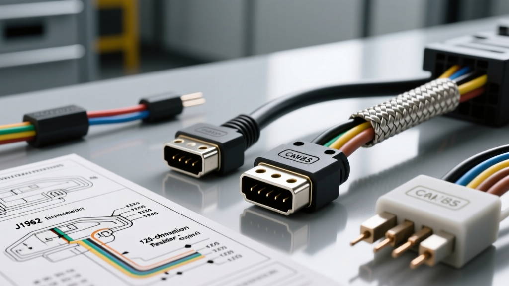
The Data Link Connector (DLC) serves as the primary diagnostic gateway for network analysis. While the SAE International J1962 standard mandates the physical 16-pin connector geometry and specific pin assignments for power, ground, and CAN lines, it does not strictly enforce wire insulation colors across all OEMs. However, identifying the correct AWG size and OEM-specific color codes is critical when tracing an electrical failure in car harnesses from the DLC back to the central gateway module.
| Pin | Function | Standard AWG | GM Wire Color (Typical) | Ford Wire Color (Typical) | Max Voltage Drop |
|---|---|---|---|---|---|
| 4 | Chassis Ground | 16 AWG | Black | Black/White | < 0.10V |
| 5 | Signal Ground | 18 AWG | Black/White | Black/Green | < 0.05V |
| 6 | CAN-High (ISO 11898) | 20 AWG (0.5mm²) | Dark Green | White | N/A (Data) |
| 14 | CAN-Low (ISO 11898) | 20 AWG (0.5mm²) | Light Green | White/Purple | N/A (Data) |
| 16 | Battery Positive (B+) | 14 AWG | Orange | Light Green/Purple | < 0.20V |
When investigating a power-related electrical failure in car DLC circuits, note that Pin 16 must supply continuous battery voltage to power scan tools and wake up modules. A voltage drop exceeding 0.20V on the B+ feed or 0.10V on the chassis ground (Pin 4) indicates high resistance in the PDC or the main ground bus, which will corrupt the transceiver's ability to read differential CAN voltages accurately.
High-Speed CAN (ISO 11898-2) Termination and Impedance
High-speed CAN networks utilize a twisted-pair topology to reject electromagnetic interference (EMI). The wires are typically twisted at a rate of 3 to 4 twists per inch. To prevent signal reflection at the ends of the bus, the network is terminated with two 120-ohm resistors placed in parallel—one at each extreme end of the CAN backbone (usually inside the ECM and the TCM or BCM). According to AA1Car's CAN Bus Diagnostic Library, measuring this termination resistance is the fastest way to identify an open-circuit electrical failure in car CAN backbones.
Expected Multimeter Readings for 120-Ohm Networks
- Normal Network: 58 to 62 ohms across Pins 6 and 14 (Key OFF, Battery Connected).
- Single Resistor Open: 118 to 122 ohms. The network may still communicate intermittently, but will be highly susceptible to EMI-induced electrical failure in car modules during high-load alternator charging.
- Both Resistors Open: Infinite resistance (OL). Complete bus failure; modules will set U-codes and default to limp mode.
- Short to Ground/Power: Measure resistance from Pin 6 to Chassis Ground, and Pin 14 to Chassis Ground. Both should read in the mega-ohm range. A reading below 10,000 ohms indicates an insulation breach or water intrusion in a harness connector.
To accurately measure termination resistance, your digital multimeter (DMM) must be set to the lowest ohms scale, and you must subtract the resistance of your test leads (typically 0.2 to 0.5 ohms) from the final reading to ensure you are within the strict 60-ohm ±5% tolerance required by OEM gateway modules.
Power Distribution Center (PDC) and Grounding Tolerances
Many network communication faults are actually disguised power supply failures. The transceivers inside control modules require a clean 5V internal logic supply, derived from an external 12V B+ feed and a pristine ground reference. If the ground reference shifts due to corrosion at the main PDC or the engine-to-chassis ground strap, the transceiver will misinterpret the differential voltage, resulting in a catastrophic electrical failure in car communication. The Bosch Semiconductor CAN Architecture guidelines emphasize that ground offset voltages exceeding 1.5V between any two nodes on the network will cause transceiver desynchronization.
| Circuit Type | Typical AWG Size | Max Allowable Voltage Drop (Loaded) | Common Failure Mode |
|---|---|---|---|
| Main Battery to PDC Feed | 4 AWG to 2 AWG | 0.10V per 10 feet | Internal PDC busbar corrosion |
| PDC to ECM/PCM B+ Feed | 12 AWG to 10 AWG | 0.15V total circuit | Fretting corrosion at module connector |
| ECM/PCM to Chassis Ground | 14 AWG to 12 AWG | 0.10V total circuit | Galvanic corrosion at engine block ring terminal |
| Sensor Signal Ground Return | 20 AWG to 18 AWG | 0.05V (50mV) total | Splice pack (S100/S200) solder joint degradation |
When performing voltage drop tests to isolate an electrical failure in car ground circuits, always test the circuit under load. A static resistance test with a DMM applies less than 1 milliamp of current, which will easily pass through a single strand of corroded copper. Use a headlamp bulb or a carbon pile load tester to draw 5 to 10 amps through the circuit while measuring the voltage drop across the suspect connection with your DMM set to the millivolt (mV) scale.
Oscilloscope Waveform Thresholds for Differential Pairs
A DMM can only display the average RMS voltage of a CAN bus, which is insufficient for diagnosing bit-level signal degradation. To properly isolate a physical layer electrical failure in car networks, a dual-channel oscilloscope is mandatory. High-speed CAN operates using differential signaling, where the data is represented by the voltage difference between CAN-High and CAN-Low, rather than their absolute voltage relative to ground.
CAN-High and CAN-Low Voltage Thresholds
- Recessive State (Logic 1): CAN-H = 2.50V, CAN-L = 2.50V. Differential Voltage = 0.0V. Both lines rest at the same potential.
- Dominant State (Logic 0): CAN-H rises to ~3.50V, CAN-L drops to ~1.50V. Differential Voltage = 2.0V.
- Short to Battery (B+): CAN-H or CAN-L locks at 12.0V. The dominant state will collapse, and the network will halt communication.
- Short to Ground: CAN-H or CAN-L locks at 0.0V. The recessive state will be pulled below the 1.5V threshold, triggering a bus-off state in the transmitting module.
When capturing waveforms, set Channel 1 to CAN-H and Channel 2 to CAN-L. Use a Math channel (Ch1 - Ch2) to view the pure differential signal. If the differential waveform shows 'ringing' (high-frequency oscillations at the edges of the dominant bits), this indicates a broken twisted pair or a missing termination resistor causing signal reflection—a highly common cause of intermittent electrical failure in car harnesses routed near high-voltage ignition coils or alternators.
Systematic Diagnostic Decision Tree
Follow this structured sequence to isolate network-level faults efficiently:
- Verify DLC Power and Ground: Check Pin 16 for B+ and Pin 4 for continuity to the battery negative post. If voltage drop exceeds 0.20V, repair the PDC feed or chassis ground before proceeding.
- Measure Termination Resistance: With the key OFF and battery connected, measure between Pins 6 and 14. If reading is 120 ohms, locate the open termination resistor. If reading is 60 ohms, proceed to step 3.
- Check for Shorts to Ground/Power: Measure resistance from Pin 6 to ground, and Pin 14 to ground. Both must be > 10k ohms. If low resistance is found, unplug modules one by one to isolate the shorted transceiver.
- Oscilloscope Validation: Back-probe Pins 6 and 14 at the DLC with the network active. Verify recessive (2.5V) and dominant (3.5V/1.5V) thresholds. Look for asymmetrical waveforms indicating a high-resistance splice or corroded connector pin.
- Module Isolation: If the physical layer specs are met but U-codes persist, suspect a software gateway fault or an internally failed module pulling down the bus voltage. Drop the network nodes one by one until the faulty module is identified.
By adhering strictly to these AWG specifications, impedance tolerances, and differential voltage thresholds, technicians can systematically eliminate guesswork and accurately repair the root cause of any network-based electrical failure in car systems.