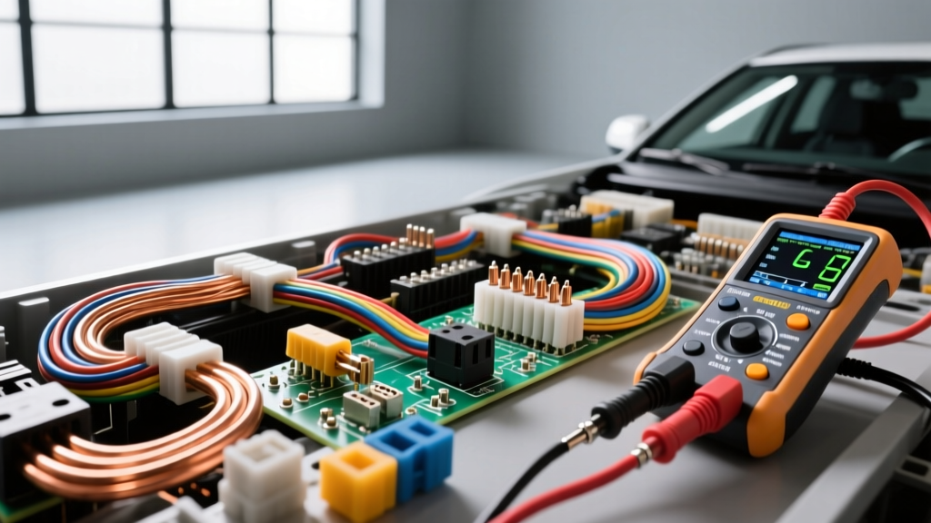
The Shift from 12V DC to Multiplexed Networks
The era of simple point-to-point 12-voltage wiring is over. Modern vehicles rely on complex multiplexed networks, pulse-width modulation (PWM), and high-speed data buses. When diagnosing auto electrical problems, selecting the correct diagnostic instrument is just as critical as understanding the wiring diagram itself. Using an outdated tool on a modern Controller Area Network (CAN) bus can yield false readings, or worse, fry a sensitive Engine Control Module (ECM) driver circuit.
This guide compares the primary diagnostic tools used by professional automotive electricians, detailing their specific applications, technical limitations, and safety parameters when probing everything from heavy-gauge starter circuits to delicate 24-gauge sensor reference lines.
Diagnostic Equipment Comparison Matrix
| Diagnostic Tool | Primary Application | Input Impedance | CAN Bus Safe? | Risk Level to ECM |
|---|---|---|---|---|
| Digital Multimeter (DMM) | Voltage drop, resistance, continuity | 10 MΩ (Standard) | Limited (Static only) | Low (if fused) |
| Automotive Oscilloscope (DSO) | Waveform analysis, CAN bus, PWM | 1 MΩ / 10 MΩ (Selectable) | Yes | Very Low |
| LED Logic Test Light | Fuse checking, basic power/ground | High (Draws <10mA) | No | Moderate |
| Incandescent Test Light | Heavy load testing (headlights, fuel pumps) | Low (Draws 250-500mA) | No | High |
| Circuit Load Tester (Power Probe) | Actuating components, forcing grounds | Variable / Active | No | Very High |
Digital Multimeters (DMM): The Baseline for Voltage Drop
A high-quality automotive DMM with a minimum input impedance of 10 Megohms (10MΩ) is the foundational tool for diagnosing auto electrical problems. According to the electrical fundamentals outlined by AutoShop 101, high impedance prevents the meter from drawing significant current, which could otherwise skew resistance readings or inadvertently trigger low-current solid-state switches.
Voltage Drop Testing Specifications
When diagnosing voltage drop across a circuit, the SAE (Society of Automotive Engineers) establishes strict thresholds to ensure adequate current delivery. A DMM is the only tool capable of measuring these minute differences while the circuit is under load.
- Connections and Terminals: Maximum allowable voltage drop is 0.10V per connection (e.g., across a single Metri-Pack 2.8 terminal or a Weather-Pack seal).
- Standard Wiring (14 AWG to 10 AWG): Total circuit voltage drop (power side + ground side) should not exceed 0.50V.
- Heavy Gauge Starter Circuits (4 AWG to 2/0 AWG): Total voltage drop across the entire cranking circuit, including the battery posts, cables, and solenoid, must remain below 0.50V. A reading of 0.65V on the ground side indicates severe corrosion at the engine block mating surface.
Expert Tip: Never pierce wire insulation with a T-pin to take voltage readings. This compromises the dielectric coating and invites copper oxidation. Always use dedicated back-probe adapters (like the Lisle 39950 set) inserted into the rear of the connector cavity to maintain the environmental seal.
Automotive Oscilloscopes: The CAN Bus Imperative
While a DMM can measure static voltage, it is entirely blind to rapid data transitions. Modern engine management and advanced driver-assistance systems (ADAS) communicate via high-speed CAN buses operating at 500 kbps (kilobits per second). To capture these signals, an automotive Digital Storage Oscilloscope (DSO) with a minimum bandwidth of 20 MHz and a sampling rate of 100 MS/s is mandatory.
Capturing J1962 DLC Waveforms
When diagnosing auto electrical problems related to network communication, technicians must probe the OBD-II J1962 Data Link Connector (DLC). The standard pinout for high-speed CAN is:
- Pin 6 (CAN High): Recessive state at 2.5V, Dominant state at 3.5V.
- Pin 14 (CAN Low): Recessive state at 2.5V, Dominant state at 1.5V.
A DMM will simply display an "average" voltage of roughly 2.6V on Pin 6 and 2.4V on Pin 14, which tells you almost nothing about the health of the network. A DSO, however, will reveal the exact square-wave topology, allowing you to spot terminating resistor failures (indicated by doubled voltage amplitudes), capacitive coupling issues, or short-to-ground faults.
For heavy-duty diesel applications utilizing SAE J1939 protocols over twisted-pair J1939 cabling (typically Green for CAN H and Yellow for CAN L), the DSO is indispensable for identifying message timeouts and arbitration errors caused by poor shield grounding.
Power Probes and Logic Testers: Proceed with Caution
Active circuit testers, commonly known as Power Probes, allow a technician to manually supply 12V power or ground to a component. While excellent for quickly actuating a fuel pump relay or testing a blower motor, they are highly dangerous when diagnosing auto electrical problems involving ECM-controlled drivers.
The Danger of Back-feeding ECM Drivers
Most modern ECMs utilize low-side drivers (sinking ground) to control injectors, ignition coils, and solenoids. These internal transistors are designed to handle specific amperage loads. If a technician uses a Power Probe to manually force 12V into an ECM-controlled ground circuit, or accidentally forces a ground into a 5V reference line, the resulting current spike will instantly destroy the ECM's internal driver, requiring a costly module replacement and reprogramming.
SRS and Airbag Circuit Warnings
Never use any active tester or standard test light on Supplemental Restraint System (SRS) circuits. SRS wiring is universally identified by yellow conduit and yellow connector housings. The airbag squibs (initiators) typically have a resistance of 1.8 to 2.2 ohms. The small amount of current drawn by a standard LED test light or the internal capacitor of a DMM is enough to inadvertently deploy an airbag or blow the SRS diagnostic fuse. Always consult OEM service information and use high-impedance breakout boxes when diagnosing auto electrical problems in the steering column clock spring or seatbelt pretensioners.
Symptom-to-Tool Decision Tree
To streamline your diagnostic process, use this decision matrix when approaching a new electrical fault:
- Symptom: Cranking System Slow / Clicking
Tool: DMM.
Action: Perform a loaded voltage drop test on the 4 AWG battery cables and engine ground strap. Verify starter solenoid trigger wire receives >10.5V during crank. - Symptom: Multiple Modules Failing to Communicate (U-Codes)
Tool: Automotive Oscilloscope (DSO).
Action: Probe DLC Pins 6 and 14. Verify CAN H and CAN L waveforms mirror each other symmetrically around the 2.5V bias line. Check for 60 ohms of parallel resistance across the bus with the battery disconnected. - Symptom: Intermittent Misfire / Sensor Dropouts
Tool: DSO with current clamp and voltage leads.
Action: Monitor the 5V reference circuit while wiggling the wiring harness. A DSO will capture microsecond voltage dips caused by a chafed 20 AWG sensor wire rubbing against the chassis that a DMM will completely miss. - Symptom: Blown Fuse Upon Activation
Tool: Short Finder / Tone Generator or Thermal Camera.
Action: Avoid using a test light or Power Probe to "clear" the short. Use a thermal imaging camera to locate the exact point where the wiring harness is pinched and generating heat against the chassis.
Conclusion
Successfully diagnosing auto electrical problems requires matching the diagnostic instrument to the specific electrical architecture of the circuit in question. Relying solely on a test light in an era of CAN bus networks and PWM-controlled alternators is a recipe for misdiagnosis. By understanding the impedance limits, voltage thresholds, and network protocols detailed above, technicians can safely and accurately isolate faults, preserving both the vehicle's sensitive electronics and the integrity of the wiring harness. For further peer-reviewed diagnostic strategies and case studies, technicians frequently consult the archives at the International Automotive Technicians Network (iATN).