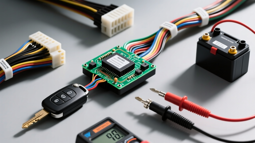
The Short Answer: RF Transmitters vs. BCM Wake States
When a customer asks, "Can a bad key fob cause electrical problems?", the immediate assumption is often that a failing fob might send a rogue voltage spike through the antenna ring, frying the Body Control Module (BCM) or immobilizer wiring harness. From an automotive electrical engineering perspective, this is a myth. The key fob is a passive, low-voltage RF (Radio Frequency) transmitter operating on 315 MHz (North America) or 433 MHz (Europe). It has no hardwired galvanic connection to the vehicle's 12V DC network.
However, a faulty key fob can and does cause severe secondary electrical problems—most notably parasitic battery drain, CAN bus sleep failures, and starter relay lockouts. When a fob's internal microswitch fails, suffers water ingress, or experiences a shorted PCB trace, it can continuously transmit an RF signal. This prevents the vehicle's Smart Key ECU, Immobilizer Transceiver, and BCM from entering their programmed sleep states. The result is a parasitic draw that can kill a Group 35 or Group 48 AGM battery overnight, leading inexperienced technicians down a rabbit hole of replacing expensive modules and tearing apart wiring harnesses.
Critical Safety Warnings & Common Diagnostic Mistakes
Before connecting a multimeter to diagnose a suspected key-fob-induced electrical drain, you must avoid the common mistakes that compromise vehicle safety and destroy diagnostic data.
Mistake #1: The 10A Multimeter Fuse Trap (Inrush Current)
The most common mistake when testing for parasitic drain caused by a BCM wake-state is blowing the multimeter's internal 10A fuse. When you disconnect the negative battery terminal to insert your meter in series, the sudden loss and restoration of power can cause multiple modules (including the BCM, ABS module, and SRS ECU) to wake up simultaneously. This inrush current easily exceeds 10A for a fraction of a second, blowing your meter's fuse and instantly dropping the network offline.
The Fix: Always use a 10 AWG copper jumper wire in parallel with your multimeter test leads when initially connecting to the negative battery post and the disconnected negative cable clamp. Leave the 10 AWG shunt wire in place for 15 minutes to allow the vehicle's CAN network to go through its normal wake/sleep cycles without interruption. Only after the modules have gone to sleep should you remove the 10 AWG wire, forcing the current to flow through the multimeter's mA or 10A port for an accurate reading.
Mistake #2: Ignoring SRS (Airbag) Wiring Proximity
When tracing wiring from the steering column lock (ESCL) or the BCM C1/C2 connectors to see if an immobilizer fault is shorting to ground, technicians often encounter Yellow-connectored wiring harnesses. These are SRS (Supplemental Restraint System) circuits. Probing these wires with a standard DMM (Digital Multimeter) or test light can deploy the airbags or permanently damage the SRS diagnostic resistor network. Never back-probe yellow connectors; rely on OBD-II DLC network testing instead.
Symptom-Cause-Fix Decision Tree: Key Fob Induced Faults
Use this structured reference to determine if the electrical symptom is actually rooted in a failing RF fob rather than a hardwired harness short.
| Observed Electrical Symptom | Common (Incorrect) Suspect | Actual Fob-Related Cause | Diagnostic Proof |
|---|---|---|---|
| Battery dead every morning (Parasitic Draw) | Shorted BCM or Trunk Harness | Stuck fob microswitch continuously transmitting 315MHz RF | Draw drops below 50mA only when fob is placed in a Faraday bag |
| CAN Bus remains awake (DLC Pin 6/14 active) | Faulty Gateway Module or Infotainment Head Unit | Fob water ingress causing intermittent 'Unlock' RF broadcasts | RF sniffer or SDR (Software Defined Radio) detects constant TX |
| Starter Relay clicks once, then locks out | Bad Neutral Safety Switch or Starter Solenoid | Fob transponder chip degrading, failing BCM cryptographic handshake | Security light flashes rapidly; OBD2 shows U-code for IMMOZ |
Advanced OBD-II DLC Network Sleep Testing
To verify if a key fob is keeping the vehicle's electrical architecture awake, you must test the CAN bus sleep state via the OBD-II Data Link Connector (DLC). According to the SAE J1962 standard, the DLC pinout provides direct access to the high-speed CAN network without needing to strip back harness tape at the BCM.
- Pin 6 (CAN-H): Typically White or White/Red wire.
- Pin 14 (CAN-L): Typically White/Blue or White wire.
Testing Procedure:
Set your DMM to DC Volts. Connect the black lead to Pin 4 (Chassis Ground) and the red lead to Pin 6 (CAN-H). With the vehicle off and doors closed, the voltage will initially hover around 2.5V to 3.5V (Awake State). If a bad key fob is continuously pinging the Smart Key antenna amplifier, the BCM will refuse to sleep, and this voltage will remain active indefinitely.
If the network is allowed to sleep (which can take up to 20 minutes on modern architectures like Toyota's Smart Key System, as documented in Toyota TIS), the CAN-H voltage should drop to near 0V, and CAN-L (Pin 14) will also drop or float depending on the OEM termination resistors. If the voltage stays at 2.5V+ after 30 minutes, and pulling the Smart Key ECU fuse drops the draw, the fob is the likely culprit.
Step-by-Step Fob Isolation Procedure
Before condemning the BCM or replacing the ignition switch assembly, follow this isolation protocol to confirm the fob is the source of the electrical parasitic drain:
- Prepare the Vehicle: Close all doors, hood, and trunk. Ensure the interior light switch is in the 'Door' or 'Off' position. Latch the hood release and use a jumper wire to trick the hood latch microswitch if necessary, allowing you to disconnect the battery while the car 'thinks' it is closed.
- Connect the Ammeter: Disconnect the negative battery terminal. Connect your multimeter (set to 10A) between the negative post and the disconnected cable clamp. Remember the 10 AWG bypass wire trick mentioned in the safety section to protect your meter.
- Wait for Sleep Mode: Wait 15 to 25 minutes. Watch the amperage. It should start high (500mA+), drop as modules shut down, and eventually settle below 50mA (0.05A).
- The Faraday Bag Test: If the draw remains high (e.g., 300mA) and the CAN bus is confirmed awake via DLC Pin 6, place the suspect key fob inside a verified RF-blocking Faraday bag, or remove its CR2032 battery entirely.
- Observe the Drop: If removing the fob's battery or shielding it causes the BCM to finally go to sleep and the amperage drops to under 50mA within 5 minutes, you have definitively proven the fob's internal PCB or tactile switch is faulty and continuously transmitting.
Real-World Failure Modes: When the Fob is Guilty
Based on extensive field diagnostics and Haynes automotive repair manuals wiring schematics, the physical wiring from the BCM to the starter relay rarely fails on its own. The true failure points related to key fobs include:
- Tactile Switch Carbon Tracking: Over time, the microscopic carbon contacts inside the fob's 'Unlock' or 'Panic' buttons degrade. This creates a high-resistance short, causing the fob to transmit a weak, continuous RF signal that isn't strong enough to unlock the doors, but is strong enough to keep the BCM's RF receiver circuit awake.
- Solder Joint Fractures: Dropping the fob can fracture the surface-mount solder joints connecting the 315MHz antenna coil to the PCB ground plane. This causes erratic impedance, leading the fob's IC to continuously reboot and transmit garbage data, flooding the CAN bus with wake-up requests.
- Water Ingress: A compromised fob seal allows moisture to bridge the 3V logic traces on the PCB, mimicking a button press and causing continuous electrical drain on the vehicle's receiver side.
By understanding that a key fob causes electrical problems via logic and network wake-states rather than direct voltage shorts, you can save hours of unnecessary harness teardowns and avoid the critical safety mistakes associated with modern immobilizer systems.