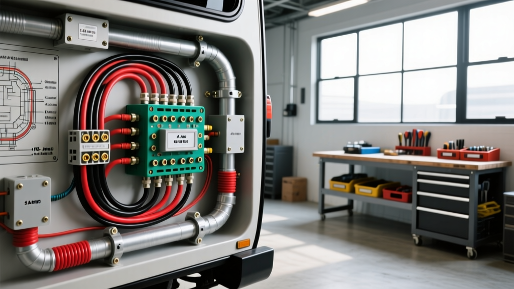
The Challenge of 100A DC Sub-Panels in Automotive and RV Platforms
When engineering the electrical architecture for Class A motorhomes, expedition overland trucks, or high-end custom off-grid vans, centralizing power distribution is critical. Adding auxiliary lighting, winches, DC-DC chargers, and heavy-duty inverter feeds requires a robust Power Distribution Unit (PDU) or auxiliary fuse block. Sizing the main feeder cable correctly is not just a matter of ampacity; it is a complex calculation involving voltage drop, thermal management, and vibration resistance. Determining the exact wire gauge for 100 amp sub panel feeds in a 12V or 24V DC automotive environment requires a departure from residential electrical codes and a strict adherence to automotive engineering standards.
SAE vs. NEC: Why Residential Wire Fails in Vehicles
A common mistake in DIY RV and automotive builds is applying National Electrical Code (NEC) principles to vehicle wiring. In residential construction, a 100-amp sub-panel is typically fed with 3 AWG or 2 AWG solid-core THHN copper wire. However, applying this to an expedition vehicle or motorhome is a critical safety hazard.
Automotive and marine environments subject wiring to constant high-frequency vibration, thermal cycling, and corrosive atmospheres. Solid-core wire will quickly work-harden, snap, and fail under chassis vibration. Furthermore, NEC ampacity tables assume static, open-air, or conduit installations, completely ignoring the bundled wiring harnesses and high ambient temperatures found inside an engine bay or behind an RV dashboard. For automotive applications, you must select wire that meets SAE J1127 (Standard for Battery Cable) or SAE J1128 (Low Tension Primary Cable) specifications. SGT (Standard Gauge Transportation) battery cable features a rugged PVC jacket and fine-strand copper (typically 2,107 strands of 30 AWG copper for 1/0 AWG), providing the necessary flexibility and resistance to vibration-induced fatigue.
Calculating the Exact Wire Gauge for 100 Amp Sub Panel Feeds
In a 12V DC system, 100 amps represents 1,200 watts of continuous power. Unlike 120V AC systems where voltage drop is a minor efficiency concern, a 12V DC system is highly sensitive to voltage loss. If your sub-panel is located 15 feet from the main battery bank, the total circuit length (positive and negative return) is 30 feet. A 3% voltage drop at 13.8V (alternator charging voltage) allows a maximum loss of 0.414V. If the wire gauge is too small, the voltage at the sub-panel busbar will drop below the operational threshold of sensitive DC-DC chargers and inverter control boards, causing them to fault out under load.
Voltage Drop Matrix: 12V DC System @ 100A Continuous Load
| One-Way Distance | Total Circuit Length | Recommended AWG (SAE SGT) | Voltage Drop % | Power Loss (Watts) |
|---|---|---|---|---|
| 5 Feet | 10 Feet | 2 AWG | 2.8% | 38.6W |
| 10 Feet | 20 Feet | 1/0 AWG | 2.5% | 34.5W |
| 15 Feet | 30 Feet | 2/0 AWG | 2.3% | 31.7W |
| 20 Feet | 40 Feet | 3/0 AWG | 2.2% | 30.3W |
Note: For 24V DC architectures (common in heavy-duty expedition trucks and military-derived platforms), you can step down one AWG size, as the higher baseline voltage halves the percentage of voltage drop for the same wattage.
Fusing and Protection: Matching the Cable to the Interrupt Rating
Selecting the wire gauge for 100 amp sub panel feeds is only half the battle; protecting that feeder cable is equally critical. Standard ANL fuses are common, but for a 100A main feeder that may experience high inrush currents (such as when large inverter capacitor banks charge), an ANL fuse can suffer from nuisance tripping or slow clearing times during a dead short. For high-capacity DC sub-panels, marine and automotive engineers recommend Class T fuses. Class T fuses offer a massive 20,000 Ampere Interrupting Capacity (AIC) at 125V DC, ensuring the fuse safely extinguishes the arc during a catastrophic short-to-ground before the 1/0 AWG or 2/0 AWG feeder cable can melt and ignite surrounding materials. The fuse must be installed within 7 inches of the main battery positive terminal, per ABYC and Painless Performance wiring guidelines.
Terminal Selection and Crimping Standards
A 100A continuous load will rapidly expose poor terminations through thermal runaway. The connection point at the sub-panel busbar and the battery terminal are the most vulnerable spots in the circuit.
- Lug Material: Use only tinned, heavy-wall copper lugs (e.g., DTNI or DTN series). Bare copper will oxidize rapidly in the presence of sulfur and moisture, creating a high-resistance layer that generates intense heat.
- Crimping Tooling: Hand-crimping 1/0 AWG or 2/0 AWG SGT cable with hammer-style crimpers is unacceptable for high-amperage DC feeds. You must use a hydraulic crimping tool with the correct hex or indenter die to achieve the required 5-ton to 15-ton compression force. This cold-welds the copper strands to the lug barrel, eliminating air pockets where moisture could infiltrate.
- Sealing: After crimping, seal the lug barrel with adhesive-lined, dual-wall heat shrink (such as 3M MDT or Raychem). The inner meltable adhesive layer flows into the wire strands, preventing 'green death' (copper oxide creep) from wicking up into the cable via capillary action.
- Hardware Torque: When securing the lugs to the sub-panel busbar, use stainless steel or silicon bronze hardware. A 5/16-inch bolt securing a 1/0 AWG lug to a copper busbar should be torqued to exactly 120 in-lbs (10 ft-lbs) using a calibrated torque wrench, and secured with a Nord-Lock washer or split-ring lock washer to prevent vibration-induced loosening.
Routing, Looming, and Firewall Pass-Throughs
Routing a massive 2/0 AWG feeder cable through an RV chassis or vehicle firewall requires careful planning to prevent chafing and short circuits. SGT cable features a relatively thick PVC jacket, but it is not immune to the sharp edges of stamped steel chassis brackets.
- Firewall Pass-Throughs: Never route high-amperage DC cables through bare metal holes. Use heavy-duty rubber firewall grommets or specialized bulkhead connectors. If drilling a new hole, deburr the edges with a chamfer tool and apply a coat of rust-inhibiting paint before installing the grommet.
- Chafing Protection: Where the cable must pass near moving suspension components, steering shafts, or exhaust headers, enclose the wire in split-loom corrugated tubing or high-temp fiberglass sleeving (for areas exceeding 200°F). Secure the loom with UV-resistant, stainless-steel barb ties or P-clamps every 12 inches.
- Separation from Signal Wires: A 100A DC feed carrying heavy, fluctuating loads (like a winch or compressor) generates a significant electromagnetic field. Route the sub-panel feeder at least 6 inches away from sensitive CAN bus networks, audio RCA cables, and ECU sensor harnesses to prevent electromagnetic interference (EMI).
Real-World Failure Modes and Troubleshooting
Even with the correct wire gauge for 100 amp sub panel installations, systems can fail if installation protocols are ignored. A common failure mode in expedition vehicles is the 'voltage drop fault' on DC-DC chargers. The charger may be rated for 100A input, but if the feeder cable is undersized or the crimps are loose, the voltage at the charger terminals may drop to 11.5V under load. The charger interprets this as a depleted battery and shuts down, leaving the auxiliary house bank uncharged. Troubleshooting requires a multimeter and a thermal camera. Under a 100A load test, use a FLIR thermal imager to scan the busbar connections and crimps. Any termination glowing hotter than the ambient wire temperature indicates a high-resistance joint requiring immediate re-termination.
Conclusion
Engineering the main feed for an automotive or RV auxiliary PDU requires a meticulous approach to wire sizing, material selection, and termination. By prioritizing SAE J1127 SGT battery cable, calculating voltage drop based on total circuit length rather than just ampacity, and utilizing hydraulic crimps with adhesive-lined heat shrink, you ensure that your 100A sub-panel delivers clean, reliable power to your vehicle's most demanding accessories. For further verification of circuit sizing and breaker coordination, consult the Blue Sea Systems Circuit Wizard and technical bulletins to validate your specific build parameters.