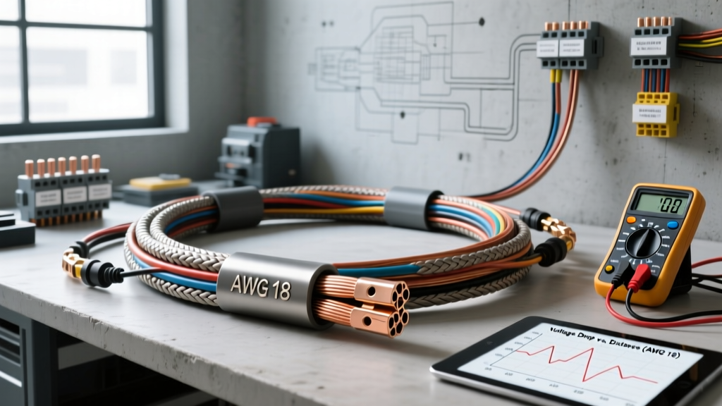
Introduction to 18 AWG in Automotive Audio
When upgrading automotive audio systems, selecting the correct conductor size is critical for preserving signal integrity, maximizing amplifier damping factor, and ensuring long-term reliability. While 16 AWG and 14 AWG conductors often dominate subwoofer and high-power discussions, 18 gauge speaker wire remains the industry standard for mid-range drivers, tweeters, component crossovers, and standard OEM-replacement door speakers. This technical specification reference outlines the electrical properties, thermal limits, and automotive application guidelines for 18 AWG audio conductors, bridging the gap between raw electrical theory and real-world vehicle installations.
Core Electrical Specifications
The American Wire Gauge (AWG) system defines the physical dimensions and electrical resistance of solid and stranded conductors. For automotive audio, 18 AWG wire provides an optimal balance of flexibility, cost, and current-carrying capacity for low-to-medium power applications. Below are the baseline specifications for standard Oxygen-Free Copper (OFC) 18 AWG wire at 20°C (68°F).
| Parameter | Specification (18 AWG OFC) |
|---|---|
| Nominal Diameter | 1.024 mm (0.0403 inches) |
| Cross-Sectional Area | 0.823 mm² |
| Resistance (OFT) | 6.385 Ohms per 1,000 feet |
| Resistance (Metric) | 20.95 Ohms per 1,000 meters |
| Max Ampacity (Chassis Wiring) | 5 to 7 Amps (depending on insulation temp rating) |
| Typical Stranding (Audio Grade) | 16 to 41 strands (per SAE J3111 flexibility classes) |
Conductor Metallurgy: OFC vs. CCA
A critical distinction in automotive speaker wire is the base metallurgy. True Oxygen-Free Copper (OFC) is the benchmark for audio conductivity. However, the market is flooded with Copper-Clad Aluminum (CCA) wire, which features an aluminum core with a thin copper electroplating. Because aluminum has roughly 61% of the conductivity of copper, an 18 AWG CCA wire exhibits approximately 30% higher electrical resistance than its OFC counterpart. In practical terms, 18 AWG CCA performs electrically closer to 20 AWG OFC. For automotive environments where run lengths from the trunk-mounted amplifier to the front doors can exceed 12 feet, the added resistance of CCA can measurably degrade high-frequency transient response and reduce overall system efficiency. Always verify the conductor material via a cross-section cut or weight test before installation.
AC Audio Signals and the Skin Effect Myth
A common audiophile misconception is that high-frequency audio signals travel exclusively on the outer edge of the wire (the skin effect), necessitating specialized stranded geometries. The skin effect is a real electromagnetic phenomenon, but its impact is dictated by frequency. At the upper limit of human hearing (20 kHz), the skin depth in copper is approximately 0.46 mm. Because the total radius of an 18 AWG conductor is roughly 0.51 mm, the skin effect is mathematically negligible across the entire audible spectrum for this gauge. Standard multi-strand 18 AWG wire is perfectly adequate for full-range audio signal transmission without requiring exotic Litz weaving or silver plating for automotive applications.
Current Capacity and Power Handling
Audio signals are Alternating Current (AC), meaning we must calculate power handling based on RMS (Root Mean Square) values rather than peak transient spikes. Using the power formula P = I²R, we can determine the current draw of a speaker. For a standard 4-ohm car audio door speaker rated at 50 Watts RMS, the continuous current draw is approximately 3.53 Amps. Since high-quality 18 AWG OFC wire is rated for 5 to 7 Amps in chassis wiring applications, it provides a safe thermal margin for 4-ohm loads up to roughly 100 Watts RMS over short distances. However, if you are wiring 2-ohm component mid-bass drivers or bridging channels, the current draw doubles, necessitating an upgrade to 16 AWG or 14 AWG to prevent thermal saturation and voltage drop.
| Speaker Impedance | Max RMS Power (18 AWG Safe Limit) | Continuous Current Draw |
|---|---|---|
| 8 Ohms | 150 Watts | 4.33 Amps |
| 4 Ohms | 75 Watts | 4.33 Amps |
| 2 Ohms | 35 Watts | 4.18 Amps |
Damping Factor and Wire Resistance
Beyond simple power delivery, speaker wire resistance directly impacts the amplifier's damping factor—its ability to control the mechanical movement of the speaker cone, particularly during bass transients. The formula for system damping factor is Z_load / (R_source + R_wire). If your amplifier has a native damping factor of 200 into a 4-ohm load, its internal output impedance is 0.02 ohms. If you use 15 feet of 18 AWG wire (total round-trip length of 30 feet), the wire adds approximately 0.19 ohms of resistance. The new system damping factor drops to roughly 19. While this drop is largely inaudible on a 6.5-inch coaxial door speaker playing midrange frequencies, it can result in 'muddy' or 'boomy' bass if 18 AWG is improperly used for a high-excursion 8-inch mid-bass driver. For dedicated subwoofers, 18 AWG should never be used.
Automotive Insulation and Routing Standards
The dielectric jacket of automotive speaker wire must withstand harsh environmental conditions, including extreme temperature cycling, UV exposure, and chemical contact from interior cleaning solvents. According to the SAE J3111 Standard for low-tension audio wire, standard PVC (Polyvinyl Chloride) jackets are sufficient for interior cabin routing. However, when routing wires through the A-pillar, under carpeting, or into the door jamb, the wire is subjected to mechanical abrasion and moisture. For these high-stress zones, technicians should utilize 18 AWG wire with a PE (Polyethylene) or Teflon (PTFE) jacket, or encase standard PVC wire in Techflex braided PET sleeving. Furthermore, when passing through the factory door-to-body rubber grommet (door boot), the wire must be highly flexible; heavily shielded or thick-jacketed 18 AWG wire can kink and eventually fracture from the repeated opening and closing of the vehicle door.
Real-World Failure Modes and Diagnostics
When troubleshooting audio distortion or channel dropouts in an aftermarket installation, 18 AWG wire connections are a primary suspect. Common failure modes include:
- Galvanic Corrosion at CCA Crimps: If CCA wire is used with standard copper crimp terminals or T-taps, moisture ingress causes rapid galvanic corrosion between the exposed aluminum core and the copper terminal, leading to an open circuit.
- Amplifier Terminal Slippage: 18 AWG wire is relatively thin. When inserted directly into the set-screw terminal blocks of high-vibration trunk-mounted amplifiers, the wire can flatten and slip out over time. Always use 4mm or 5mm copper ferrule pins crimped onto the 18 AWG wire before securing it into amplifier or DSP (Digital Signal Processor) terminal blocks.
- OEM Harness Adapter Mismatches: When using adapters like the Metra 72-8104 (Toyota) or Scosche SA10, the factory wiring is often 20 or 22 AWG. Splicing a thick, stiff 16 AWG wire to a delicate 22 AWG factory pigtail creates a mechanical stress point. Using 18 AWG wire for the final 12 inches of the run provides a much safer, more flexible transition to factory harness connectors.
Authoritative References
For further technical validation regarding automotive wire sizing, dielectric properties, and audio signal transmission, consult the following industry standards and engineering resources: