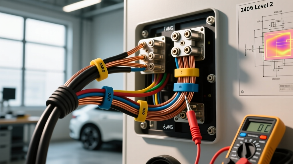
Introduction to 240V Automotive Charging Systems
While traditional automotive electrical systems operate on 12V or 48V DC architectures, the rapid adoption of Electric Vehicles (EVs) and Plug-in Hybrid Electric Vehicles (PHEVs) has introduced high-voltage AC infrastructure into the automotive service bay and residential garage. Level 2 Electric Vehicle Supply Equipment (EVSE) operates on 240V split-phase AC power. Because EV charging is classified as a continuous load—defined by the National Electrical Code (NEC) as a load where the maximum current is expected to continue for three hours or more—selecting and verifying the correct wire gauge for 240v applications is critical. Undersized conductors in EV charging circuits lead to severe voltage drop, thermal throttling, melted NEMA receptacles, and potentially catastrophic electrical fires.
This guide provides a step-by-step troubleshooting flow for automotive electrical technicians and advanced DIYers to diagnose, verify, and correct wire gauge and termination issues in 240V EV charging systems.
Step 1: Symptom Identification and Initial Safety Protocols
Before opening any EVSE enclosure or testing 240V circuits, technicians must recognize the common failure symptoms associated with improper wire sizing. Because the onboard charger (OBC) and the EVSE communicate via the SAE J1772 Control Pilot (CP) signal, the vehicle will often attempt to draw the maximum current advertised by the EVSE. If the wiring cannot handle the thermal load, the system will exhibit specific failure modes.
Common Symptoms of Undersized 240V Wiring
- EVSE Thermal Throttling: The charging session starts normally but drops from 40A to 16A or shuts down entirely after 20-30 minutes due to internal thermal sensors detecting excessive heat at the terminal blocks.
- Melted or Discolored Plugs: The NEMA 14-50 or NEMA 6-50 plug pins show heat bluing, melted plastic housings, or carbon scoring.
- Nuisance Breaker Tripping: The dedicated 240V circuit breaker trips after extended charging sessions, indicating thermal overload rather than a short circuit.
- Proximity Pilot Faults: The vehicle dashboard displays a "Check Charge Port" or "AC Charging Fault" code, often triggered by voltage sag falling below the OBC's minimum operational threshold (typically around 210V AC).
Safety Warning: Always use a CAT III or CAT IV rated digital multimeter (DMM) and wear appropriate PPE. Verify zero energy state using the Live-Dead-Live method before touching any terminal blocks inside the EVSE.
Step 2: Verifying the Correct Wire Gauge for 240v Loads
The most common troubleshooting failure occurs when an installer uses standard residential sizing logic rather than continuous-load automotive EVSE logic. According to NFPA 70 (NEC) Article 625, EV charging circuits must be derated to 80% of the breaker's maximum capacity, or conversely, the wire and breaker must be sized at 125% of the continuous charging load.
240V EVSE Wire Gauge Specification Chart
| EVSE Max Output | Continuous Load (100%) | Required Breaker | Min Copper AWG (60°C/75°C) | Typical Application |
|---|---|---|---|---|
| 16 Amps | 16A | 20A | 12 AWG | Portable 240V cords |
| 24 Amps | 24A | 30A | 10 AWG | Older/Compact wall units |
| 32 Amps | 32A | 40A | 8 AWG | Standard 7.7kW OBC vehicles |
| 40 Amps | 40A | 50A | 6 AWG | Tesla Wall Connector / 9.6kW |
| 48 Amps | 48A | 60A | 4 AWG | 11.5kW High-Power OBC |
| 80 Amps | 80A | 100A | 1/0 AWG | Commercial / Fleet DC fast-charge prep |
Troubleshooting Action: The SAE J1772 PWM Signal Check
If you suspect the wrong wire gauge was installed for the EVSE's configured output, you must verify the Control Pilot (CP) Pulse Width Modulation (PWM) signal. The EVSE tells the vehicle how much current is available via a 1kHz square wave on the CP pin. For example, a 40A continuous load requires an 80% duty cycle. If an installer wired a 48A EVSE using 6 AWG wire (rated for 50A breaker / 40A continuous), the wire will overheat when the EVSE broadcasts an 80% duty cycle (48A). Use an oscilloscope to read the CP pin. If the duty cycle exceeds the safe capacity of the installed wire gauge, the EVSE internal DIP switches or software configuration must be downgraded immediately.
Step 3: Performing Under-Load Voltage Drop Tests
Static voltage testing is useless for diagnosing wire gauge issues in high-amperage automotive charging circuits. A circuit with 10 AWG wire on a 60A breaker might show 242V AC at the EVSE terminals when idle, but will suffer massive voltage sag when the vehicle's OBC engages the contactors and pulls 48A.
The Voltage Drop Testing Flow
- Establish Baseline: Measure the open-circuit voltage at the main service panel breaker terminals (L1 to L2). Record this value (e.g., 245V).
- Initiate Charge: Plug the EVSE into the vehicle and initiate a charging session. Ensure the vehicle is set to accept maximum amperage via the infotainment or mobile app.
- Measure Under Load: Using a CAT III DMM, carefully measure the voltage directly at the EVSE internal terminal blocks (where the Black L1 and Red L2 wires land on the contactor/board). Do not test at the receptacle; test at the EVSE termination point to isolate the branch circuit wiring.
- Calculate Drop: Subtract the under-load EVSE voltage from the baseline panel voltage. According to DOV EV Charging Infrastructure Guidelines, branch circuits should not exceed a 3% voltage drop (7.2V on a 240V system).
Diagnostic Matrix:
- Drop < 3% (e.g., 5V): Wire gauge is correctly sized for the distance and load.
- Drop 3% - 5% (e.g., 10V): Wire is technically undersized for the run length, or operating at maximum thermal capacity. Upsizing one AWG step is recommended.
- Drop > 5% (e.g., 15V+): Severe undersizing, loose termination, or aluminum wire oxidation. Immediate circuit shutdown required.
Step 4: Termination and Connector Troubleshooting
Frequently, the wire gauge for 240v circuits is mathematically correct, but the physical termination creates a high-resistance bottleneck that mimics an undersized wire. In automotive and EVSE applications, vibration and thermal cycling cause screw terminals to loosen over time.
Inspecting NEMA 14-50 and Hardwired Terminations
The NEMA 14-50 receptacle is the most common 240V EV charging outlet. It utilizes four pins: X (L1 - Black), Y (L2 - Red), W (Neutral - White), and G (Ground - Green). The Neutral pin is largely unused by modern EVSEs unless the unit requires 120V for internal logic boards, but the Ground pin is critical for the equipment grounding conductor (EGC) and fault detection.
Torque Specifications and Thermal Imaging
Hand-tightening terminal screws is a primary cause of EVSE fires. You must use a calibrated inch-pound torque screwdriver.
- NEMA 14-50R Receptacle Terminals: Typically require 25 to 35 in-lbs of torque. Verify the wire is stripped to the exact length indicated by the gauge on the device (usually 3/4 inch).
- EVSE Internal Terminal Blocks: Hardwired units accepting 6 AWG or 4 AWG stranded wire often require 45 to 50 in-lbs. Always use ferrule crimps on stranded wire if the EVSE manufacturer specifies it to prevent wire splaying, which reduces the effective contact surface area and increases resistance.
Pro-Tip: Use a FLIR thermal imaging camera after the vehicle has been charging for 30 minutes. A properly sized and torqued 240V circuit should show a uniform temperature distribution. If you see a localized hot spot (delta T > 20°C above ambient) at a specific terminal screw, the issue is a loose connection or a damaged wire strand, not necessarily the overall AWG rating.
Common Failure Modes: Aluminum vs. Copper and Stranding
When troubleshooting older installations or commercial fleet depots, technicians frequently encounter aluminum (AL) wiring. While aluminum is an acceptable conductor for high-amperage 240V feeders, it requires specific anti-oxidant compound (Noalox) and torque adjustments. Furthermore, aluminum creeps under pressure, meaning a terminal torqued perfectly on day one will loosen by month six due to thermal expansion and contraction cycles. If an EVSE is connected to an aluminum branch circuit, the wire gauge must be upsized by at least one to two AWG sizes compared to copper equivalents, and terminations must be re-torqued annually.
Additionally, ensure the EVSE terminal block is rated for stranded wire. Some residential-grade 240V disconnects and receptacles are rated only for solid copper wire. Inserting 6 AWG stranded EVSE wire into a solid-only terminal will result in crushed strands, high resistance, and eventual melting. Always consult the SAE J1772 standard documentation and the specific EVSE installation manual for termination compatibility.
Summary Checklist for Technicians
When dispatched to diagnose an EV charging fault, follow this sequence:
- Verify the EVSE configured amperage via PWM duty cycle.
- Confirm the breaker size and wire AWG meet the 125% continuous load rule (NEC Article 625).
- Perform an under-load voltage drop test at the EVSE terminals.
- Inspect terminations with a thermal camera and verify torque specs.
- Check for aluminum wire creep or stranded wire splaying.
By systematically isolating the electrical infrastructure from the vehicle's onboard charger, technicians can accurately resolve 240V wire gauge and termination issues, ensuring safe, efficient, and uninterrupted EV charging.