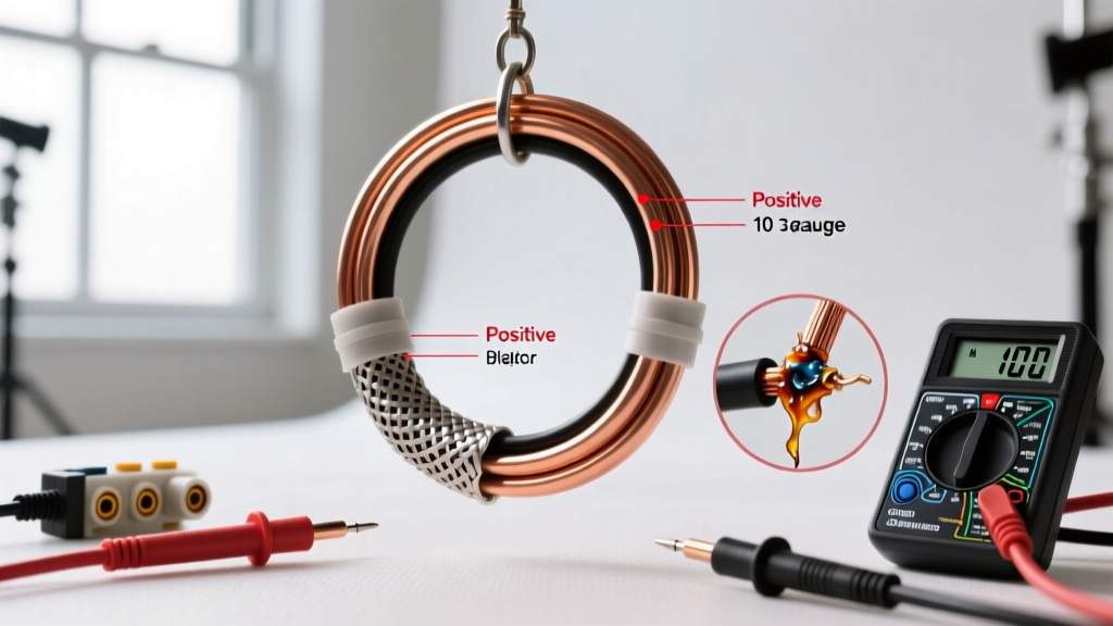
Baseline Specifications: How Many Amps Can 10 AWG Safely Carry?
When diagnosing automotive electrical faults, understanding the exact ampacity of your conductors is the first step in isolating failures. 10 AWG wire (5.26 mm² cross-sectional area) serves as the critical bridge between standard 14-16 AWG lighting circuits and heavy 4-8 AWG battery cables. It is the standard choice for feeding secondary fuse blocks, high-draw auxiliary lighting relays, and electric fan controllers. However, answering the question of how many amps 10 gauge wire can safely carry requires distinguishing between chassis wiring in free air and bundled automotive harnesses.
According to the SAE J1128 Automotive Wire Standard, the current-carrying capacity of a wire drops significantly when bundled with other conductors due to thermal accumulation. Below is the technical baseline for 10 AWG copper wire with standard GXL (cross-linked polyethylene) insulation rated for 125°C.
| Parameter | 10 AWG (5.26 mm²) Specification |
|---|---|
| Nominal Diameter (Bare) | 2.588 mm |
| Resistance @ 20°C | 1.018 Ω / 1,000 ft |
| Max Ampacity (Single Wire, Free Air) | 30 Amps Continuous |
| Max Ampacity (Bundled 7-Wire Harness) | 24 Amps Continuous |
| Recommended Fusing (Maxi-Fuse) | 30A or 40A Slow-Blow |
Step-by-Step Troubleshooting Flow: Diagnosing 10 AWG Circuit Failures
When a 10 AWG circuit exhibits symptoms of failure—ranging from nuisance fuse blowing to melted terminal housings—technicians must follow a systematic decision tree. Use the following troubleshooting flow to isolate the root cause of the fault.
Branch A: Insulation Discoloration, Stiffness, or Melting
Symptom: The GXL or TXL insulation on the 10 AWG wire feels brittle, shows brown scorch marks near the ring terminal, or has melted at the connector housing.
Diagnostic Step 1: Thermal Imaging & Touch Test. With the circuit under continuous load, use an infrared thermal camera or carefully touch the wire runs. If the wire is hot along its entire length, the circuit is exceeding the 24A-30A bundled ampacity limit. If the heat is localized entirely at the termination point (crimp or screw), the wire gauge is fine, but you have a high-resistance connection.
Diagnostic Step 2: Verify Termination Torque. A common failure mode occurs when 10 AWG ring terminals are secured to a busbar (like a Blue Sea Systems ST Blade block) without a torque wrench. The specification for a #10 stainless steel terminal screw is typically 120 in-lbs (13.5 Nm). Under-torquing causes micro-arcing and localized melting.
Corrective Action: If the whole wire is hot, upgrade to 8 AWG. If the heat is localized, cut back the wire to bare copper, apply a fresh adhesive-lined heat shrink crimp using a #10 AWG hex die, and re-torque the terminal.
Branch B: Excessive Voltage Drop Under Load
Symptom: An accessory (such as an ARB Twin Motor Air Compressor or a 50-inch LED light bar) operates sluggishly, or an ECU tap throws a low-voltage code, despite the 30A fuse remaining intact.
Diagnostic Step 1: Measure Voltage Drop (V-drop). Set your digital multimeter to DC Volts. Place the red probe on the battery positive post and the black probe on the accessory's positive input pin while the accessory is actively drawing current.
Diagnostic Step 2: Calculate Expected Drop. The formula for V-drop is: V = (2 x Length x Current x Resistance) / 1000. For a 15-foot run of 10 AWG wire carrying 25 Amps, the calculation is: (2 x 15 x 25 x 1.018) / 1000 = 0.76 Volts.
Diagnostic Step 3: Evaluate Tolerance. For a resistive load like an LED light bar, a 0.76V drop (resulting in 11.24V at the load on a 12V system) is acceptable. However, if this 10 AWG wire is feeding a sensitive ECU pin or a modern solid-state relay requiring strict 12.5V+ logic, 0.76V is a failure.
Corrective Action: If the measured V-drop exceeds your calculated baseline by more than 0.2V, you have internal wire corrosion or a failing intermediate splice. If the calculated baseline itself is too high for the device, you must upsize to 8 AWG or shorten the wire run.
Branch C: Nuisance Fuse Blowing (30A Maxi-Fuse)
Symptom: The 30A Maxi-fuse protecting the 10 AWG feed to an auxiliary fuse block blows intermittently, usually upon startup of connected accessories.
Diagnostic Step 1: Clamp Meter Inrush Analysis. Hook a DC clamp meter with peak-hold/inrush capability around the 10 AWG wire. Trigger the accessory. Electric motors (like fuel pumps, winch solenoids, or radiator fans) experience an inrush current that can spike to 150% of their continuous draw for 200-500 milliseconds. A 20A radiator fan can momentarily pull 35A on startup.
Diagnostic Step 2: Fuse Characteristic Matching. Standard automotive blade fuses are fast-acting. If your 10 AWG wire is protected by a standard 30A ATO/Maxi fuse, the inrush spike will fatigue the fuse element, leading to a nuisance blow even though the wire is perfectly safe handling the brief thermal spike.
Corrective Action: Replace the standard Maxi-fuse with a 30A or 40A Time-Delay (Slow-Blow) MIDI or AME fuse. This allows the inrush spike to pass without compromising the continuous thermal protection of the 10 AWG wire. For deeper insights into fuse curve matching, consult the Painless Performance Technical Manuals regarding high-amperage auxiliary circuits.
Connector Pairings and Pin Configurations for 10 AWG
A frequent failure mode in custom harness building is attempting to force 10 AWG wire into connectors designed for smaller gauges. Standard Delphi Weather-Pack connectors max out at 12 AWG. Forcing 10 AWG into these pins results in splayed wire strands, high resistance, and eventual housing melt-down.
- Delphi Metri-Pack 280 Series: Rated for up to 30 Amps. Use terminal part number 15324983 (female) and 15324984 (male), which are specifically stamped to accept 10-12 AWG wire. Ensure the wire seal (part 15324973) is fully seated to prevent moisture ingress.
- Anderson Powerpole SB50: Ideal for quick-disconnect 10 AWG applications like winch remotes or auxiliary battery boxes. Requires a specific #10 AWG crimp die to form the proper hex shape on the contact barrel.
- Deutsch DT Series: Standard DT contacts only accept up to 14 AWG. If you must interface a 10 AWG feed into a Deutsch housing, you must use a Deutsch HD Series (HD10 or HDP20) connector, which utilizes heavier #12 or #10 AWG solid pin contacts.
Real-World Case Study: EV Battery Management System (BMS) Tap
In custom EV conversions, 10 AWG wire is frequently used to tap the main battery pack to feed a high-voltage to 12V DC-DC converter. The wire color code for this high-draw 12V output is typically Red with a White Tracer to distinguish it from standard ignition-switched 12V (which is usually solid Red or Pink). If the DC-DC converter pulls a continuous 28A, running the 10 AWG wire through a firewall grommet alongside CAN-bus twisted pairs (typically 22 AWG) will cause the CAN-bus to suffer from electromagnetic interference (EMI) and thermal degradation. Always route 10 AWG high-amperage feeds at least 6 inches away from low-voltage data lines, and utilize a braided copper shielding sleeve if proximity is unavoidable.
Summary Checklist for 10 AWG Verification
- Verify the wire is true 10 AWG (5.26 mm²) and not Copper-Clad Aluminum (CCA), which has 40% higher resistance and will overheat at 25A.
- Confirm the circuit is protected by a Time-Delay fuse sized no higher than 40A.
- Ensure all crimps are performed with a ratcheting hex-crimp tool specific to 10 AWG, and all busbar terminations are torqued to 120 in-lbs.
- Measure voltage drop under maximum continuous load; it should not exceed 3% (0.36V) for sensitive electronics or 5% (0.6V) for resistive loads.
For further reference on terminal crimp specifications and pull-out force requirements for heavy-gauge automotive connectors, review the Waytek Automotive Connector Catalog and cross-reference your specific terminal part numbers.