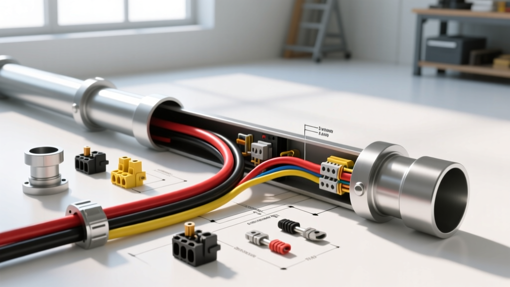
Diagnostic Flow: Troubleshooting Conduit for 6 Gauge Wire
Routing high-amperage automotive and marine circuits requires precise attention to physical protection and thermal management. When sizing conduit for 6 gauge wire, technicians frequently encounter issues ranging from pull-tension jamming to catastrophic thermal derating. A standard 6 AWG conductor (26,240 Circular Mils, 0.162-inch bare diameter) is the backbone for 150A+ alternator upgrades, rear-mounted 12,000 lb winch feeds, and EV battery module balancing. However, placing this heavy-gauge wire into the wrong conduit environment leads to voltage drop, insulation failure, and fire hazards.
This step-by-step troubleshooting flow is designed for automotive electrical experts and marine riggers to diagnose and resolve conduit sizing, fill capacity, and routing failures specific to 6 AWG applications.
Reference Table: 6 AWG Wire Dimensions & Conduit Fill
Before troubleshooting a physical routing issue, verify your baseline measurements. Automotive wire (SAE J1128) has significantly thicker insulation than building wire (NEC THHN), which drastically alters conduit fill capacities and jam ratios. According to the SAE J1128 Standard for Battery Cable, the outer diameter (OD) varies by insulation type.
| Wire Type | Insulation Wall | Approx. OD | Min. Recommended Conduit ID (Single) | Jam Ratio Risk |
|---|---|---|---|---|
| 6 AWG SXL (Auto) | 0.030' | 0.222' | 0.375' (3/8' Loom) | High in 1/2' PVC at bends |
| 6 AWG GXL (Auto) | 0.023' | 0.208' | 0.375' (3/8' Loom) | Moderate in 1/2' PVC |
| 6 AWG THHN (Marine/Industrial) | 0.030' (Nylon/PVC) | 0.184' | 0.250' (1/4' Loom) | Low in 1/2' PVC |
| 6 AWG Welding Cable | 0.040' (EPDM) | 0.242' | 0.500' (1/2' Loom) | Severe in 1/2' PVC |
Note: The NFPA 70 National Electrical Code (NEC) Chapter 9 Table 1 mandates a 40% maximum fill capacity for three or more conductors in a raceway. For a single 6 AWG SXL wire, 40% fill allows a minimum conduit ID of 0.35 inches.
Troubleshooting Decision Tree: Symptom to Solution
Use the following diagnostic flow to identify why your 6 AWG conduit installation is failing or presenting routing anomalies.
Symptom 1: Wire Jamming and High Pull Tension
Observation: The 6 AWG wire binds, kinks, or refuses to pull through the conduit at elbow joints or firewall grommets. Pulling compound fails to reduce friction.
- Step 1: Calculate the Jam Ratio. Divide the Conduit Inner Diameter (ID) by the Wire Outer Diameter (OD). If the result is between 2.8 and 3.2, the wire will physically wedge against the outside wall of the conduit bend.
- Step 2: Check Conduit Trade Size. If you are using 1/2-inch Schedule 40 PVC (ID = 0.622') for three runs of 6 AWG SXL (OD = 0.222'), the Jam Ratio is 2.8. This is the exact mathematical threshold for jamming.
- Step 3: The Fix. Upsize to 3/4-inch PVC (ID = 0.824') or switch to a single-conductor flexible braided sleeving. If routing through a vehicle firewall, abandon rigid conduit at the bend and use a 90-degree angled rubber firewall bulkhead connector (e.g., 1/2' ID grommet) to eliminate the sweep radius entirely.
Symptom 2: Thermal Overheating & Voltage Drop
Observation: A 150A alternator feed (Red 6 AWG SXL) enclosed in black corrugated split loom under the hood is exhibiting melted insulation near the exhaust manifold, accompanied by a 0.8V drop at the battery terminals under load.
- Step 1: Evaluate Ambient & Trapped Heat. Standard corrugated nylon split loom is rated to 125°C, but black loom absorbs radiant heat from exhaust headers. Furthermore, conduit traps stagnant air, preventing convective cooling of the 6 AWG copper strands.
- Step 2: Verify Ampacity Derating. While 6 AWG copper can handle 75A-100A continuously in free air (per Painless Performance Products Wiring Manuals), bundling it inside an unvented conduit in a 100°C engine bay severely derates its current-carrying capacity.
- Step 3: The Fix. Remove the plastic corrugated loom in the engine bay. Replace it with high-temperature fiberglass braided sleeving (rated to 500°C) or silicone-coated fiberglass wrap. Ensure the conduit has weep holes or is left open-ended at the firewall to allow under-hood air pressure to force convective airflow through the sleeve.
Symptom 3: Insulation Chafing & Intermittent Ground Faults
Observation: A rear-mounted winch power feed (Black 6 AWG welding cable) routed along the chassis frame rail inside rigid plastic conduit is tripping the 175A Mega Fuse intermittently when the vehicle articulates off-road.
- Step 1: Inspect for Micro-Vibration Chafing. Heavy-gauge wire is incredibly stiff. When the chassis flexes, the 6 AWG wire acts as a battering ram inside the conduit, grinding away the insulation at the conduit entry and exit points.
- Step 2: Check for Missing Bushings. Cut conduit leaves razor-sharp micro-barbs. Even if the wire pulled through cleanly, frame vibration will saw the 6 AWG SXL insulation down to the bare copper within 500 miles of off-road driving.
- Step 3: The Fix. Install flared nylon conduit terminations or rubber grommets at every entry/exit point. Wrap the 6 AWG wire in friction tape (e.g., Tesa 51036 PET fleece tape) specifically at the conduit ends to provide a sacrificial chafe barrier. Secure the conduit to the frame rail every 8 inches using UV-resistant stainless steel P-clamps with rubber cushions to prevent resonance transfer.
Symptom 4: Moisture Ingress & Galvanic Corrosion
Observation: Marine windlass feeds or EV battery cables routed in sealed conduit show green/white copper oxide buildup at the 3/8' ring terminals, leading to high resistance and terminal heat.
- Step 1: Identify the Capillary Effect. If a conduit run has a low point (a sag) and is not perfectly sealed, moisture enters via condensation or splash. The stranded 6 AWG copper acts as a wick, drawing water via capillary action directly into the crimp barrel of the terminal.
- Step 2: Check Conduit Sealing Method. Using standard electrical tape at conduit ends fails due to adhesive breakdown from heat and solvents.
- Step 3: The Fix. Implement a drip loop before the wire enters the terminal enclosure. Seal conduit ends using adhesive-lined dual-wall heat shrink tubing (minimum 3:1 shrink ratio) that bonds simultaneously to the conduit OD and the wire insulation. Inject dielectric grease or marine-grade terminal sealant into the crimp barrel prior to crimping the 3/8' ring terminal.
Advanced Routing: Bend Radius Limits for 6 AWG
When fabricating custom metal or rigid PVC conduit for 6 AWG wire, you must respect the minimum bend radius to avoid stretching the copper strands, which increases localized resistance. For 6 AWG stranded automotive wire, the absolute minimum bend radius is 4 times the outer diameter of the wire. For SXL wire (0.222' OD), the wire itself requires a minimum bend radius of 0.88 inches. Therefore, your conduit sweep must have an inner radius of at least 1.5 inches to accommodate the wire's natural tendency to push against the outer wall of the curve. Using a heat gun to soften 6 AWG insulation before pulling through tight conduit radii is a common but flawed practice; it alters the crystalline structure of the cross-linked polyethylene, reducing its dielectric strength and thermal rating.
Summary of Best Practices
Sizing conduit for 6 gauge wire is not merely about physical fit; it is an exercise in thermal dynamics and mechanical stress management. Always calculate the Jam Ratio for multi-conductor pulls, prioritize convective airflow in high-heat engine bays, and mandate sacrificial chafe protection at all conduit terminations. By following this diagnostic flow, you ensure that your high-amperage automotive and marine circuits deliver maximum efficiency without the risk of catastrophic insulation failure.