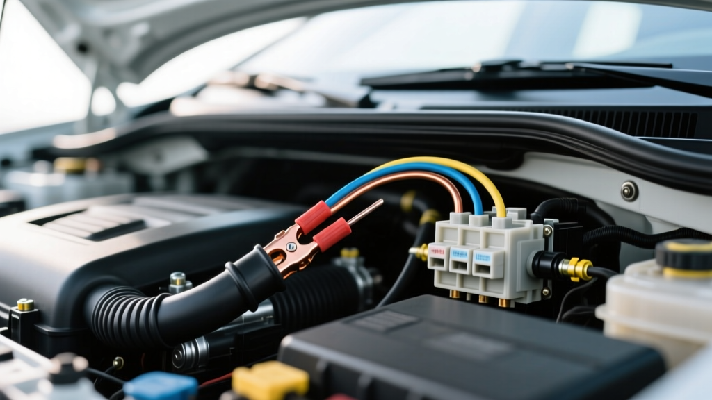
Why 10 AWG is the Standard for 30A Automotive AC Circuits
When executing an upgrade or modification project involving high-draw cooling systems—such as installing a 12V Dometic rooftop air conditioner on a Sprinter van, or wiring a heavy-duty Red Dot auxiliary AC compressor for an off-road overland rig—circuit sizing is critical. Using 10 gauge wire for air conditioner circuits is the industry baseline for 30-amp continuous draw applications. According to the SAE J1128 Low Tension Primary Cable Standard, 10 AWG copper wire is rated for up to 30 amps in engine bay environments where ambient temperatures can exceed 100°C.
Standard automotive AC clutch circuits typically only draw 3 to 5 amps, requiring just 16 or 18 AWG wire. However, modern 12V electric compressors (often used in EV swaps or auxiliary cabin coolers) and RV rooftop AC fan/compressor combos can pull 20 to 28 amps under locked-rotor or high-heat conditions. If you undersize this wire, the resulting voltage drop will starve the compressor, leading to rapid clutch cycling, burnt windings, and melted insulation.
The Physics of Voltage Drop in 10 AWG Copper
Pure annealed copper 10 AWG wire has a resistance of approximately 1.018 ohms per 1,000 feet. In a typical van build or off-road truck modification, the round-trip wire run (from the battery busbar, through the firewall or roof gland, to the AC unit, and back to the chassis ground) is often 30 to 40 feet.
Using Ohm’s Law (V = I × R), a 25-amp draw across 40 feet of 10 AWG wire results in a voltage drop of roughly 1.01 volts. In a 13.8V charging system, a 1.01V drop represents a 7.3% loss. While this is slightly above the ideal 3% limit for sensitive electronics, it is perfectly acceptable for the inductive loads of an AC compressor motor. If your specific modification requires a run longer than 50 feet round-trip, you must step up to 8 AWG to maintain optimal compressor efficiency.
Selecting the Correct Wire Jacket: GXL vs. TXL vs. THHN
A common and dangerous mistake in automotive modification projects is using residential THHN or stranded PVC hook-up wire. PVC insulation begins to soften and melt at 105°C. When routed near an engine block, exhaust manifold, or auxiliary heater, PVC-jacketed wire will short out against the chassis, causing an electrical fire.
For any automotive 10 gauge wire for air conditioner routing, you must specify cross-linked polyethylene (XLPE) jacketed wire. The Pacer Group Wire Gauge and Ampacity Chart outlines the specific automotive standards you should source:
- GXL (General Cross-Linked): The standard for under-hood routing. Features a 125°C temperature rating and a durable, abrasion-resistant jacket. Ideal for routing from the alternator/battery to the firewall.
- TXL (Thin-Wall Cross-Linked): Features the same 125°C rating as GXL but with a thinner insulation wall. This makes it lighter and more flexible, perfect for tight looms and conduit runs inside the cabin or roof cavity where flexibility is needed but heat is less of a concern.
- SXL (Special Cross-Linked): The thickest jacket available, rated for extreme abrasion and high heat. Use SXL only if the 10 AWG wire must pass directly over an exhaust header without the protection of a split loom or heat shielding.
Step-by-Step: Routing and Firewall Penetration
When routing your 10 AWG main power feed for the AC compressor or rooftop unit, physical protection is just as important as electrical sizing.
- The Drip Loop: If routing wire from an exterior rooftop AC gland into the cabin, always create a "drip loop" below the entry point before the wire rises to the terminal block. This prevents condensation and rainwater from tracking down the wire jacket directly into your busbar or breaker.
- Firewall Grommets: Never pass bare 10 AWG wire through a metal bulkhead or firewall. Use a stepped rubber firewall grommet. Apply a small amount of silicone dielectric grease to the wire jacket to help it slide through the grommet without tearing the rubber seal.
- Split Loom and Tesa Tape: Inside the engine bay, wrap the 10 AWG wire in corrugated split loom. Inside the cabin or roof cavity, wrap the wire in Tesa 51036 PET fleece tape. Fleece tape prevents the wire from rattling against the sheet metal, eliminating the "buzzing" sound often heard in the cabin when the AC compressor engages.
Termination and Crimping Specifications
A 30-amp AC circuit will generate significant heat at any point of high resistance. A poorly crimped terminal will act as a resistor, generating heat that can melt the terminal housing. You must use a closed-barrel ratcheting crimper (such as the TE Connectivity Certi-Crimp or Knipex 97 52 34) and adhesive-lined heat shrink.
| Component | Specification / Size | Application Notes |
|---|---|---|
| Terminal Type | Closed-Barrel Ring | Prevents wire strands from splaying under high-vibration AC compressor operation. |
| Stud Size | 5/16" (M8) | Standard for 30A MIDI fuse holders and auxiliary busbars. |
| Wire Strip Length | 11mm (7/16") | Strands should be flush with the end of the crimp barrel; do not trim them. |
| Crimp Tool Die | Red / 12-10 AWG | Use the red die on ratcheting tools to ensure the correct compression ratio. |
| Heat Shrink | 3M EPS400 (Dual-Wall) | Must contain hot-melt adhesive to seal out moisture and prevent corrosion. |
| Torque Spec (Busbar) | 12-15 Nm | Overtightening a 5/16" stud can snap the terminal post on plastic fuse blocks. |
Fusing and Relay Architecture for High-Draw AC
The Blue Sea Systems Circuit Protection Guide mandates that overcurrent protection must be installed within 7 inches of the power source (battery or main busbar). For a 10 AWG wire feeding a 30A air conditioner circuit, a standard 30A automotive blade fuse (ATO/ATC) is insufficient. Blade fuses are prone to terminal spreading and heat buildup at continuous 25A+ draws.
Instead, utilize a 30A MIDI (AME) fuse or a 40A ANL fuse housed in a sealed, marine-grade fuse block. MIDI fuses are specifically designed for high-amperage, continuous-duty automotive circuits like electric AC compressors and auxiliary winch solenoids. Furthermore, do not rely on a standard 30A Bosch-style relay to switch the compressor. The internal contacts of cheap relays will arc and pit under the inductive kickback of an AC motor. Use a heavy-duty contactor or a solid-state relay (SSR) rated for at least 50A to ensure longevity.
Troubleshooting Decision Tree: AC Compressor Voltage Drop
If your aftermarket AC unit is short-cycling or failing to engage, use this diagnostic tree to isolate the fault in your 10 AWG circuit:
- Symptom: Compressor clicks rapidly but does not spin.
- Step 1: Measure voltage at the battery while the relay clicks. If battery voltage remains above 12.5V, proceed to Step 2.
- Step 2: Measure voltage directly at the compressor terminal while engaged. If voltage drops below 10.5V, you have excessive resistance in the 10 AWG wire run or a corroded ground.
- Fix: Inspect all ring terminals for green copper oxide. Re-crimp using adhesive-lined heat shrink and verify chassis ground is sanded to bare metal.
- Symptom: Wire insulation near the fuse block feels hot to the touch after 10 minutes of AC runtime.
- Step 1: Check the crimp connection. A hot wire near the terminal indicates a poor mechanical crimp, not an undersized wire.
- Fix: Cut back the wire by 1 inch to remove oxidized copper and perform a new crimp with a properly calibrated ratcheting tool.
By adhering to SAE standards, utilizing XLPE-jacketed 10 AWG copper, and executing flawless terminations, your automotive air conditioning upgrade will deliver reliable, high-output cooling without the risk of thermal failure.