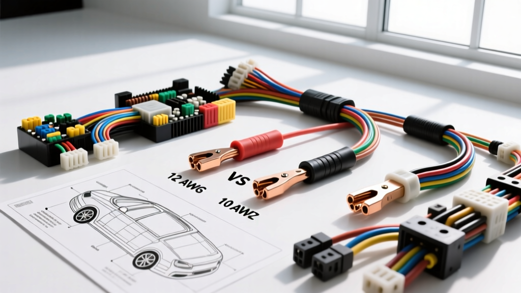
Determining What Gauge Wire for 20amp Automotive Circuits
When automotive technicians, marine electricians, and motorsport engineers ask, "what gauge wire for 20amp circuits," the immediate reflex is often 12 AWG. However, applying National Electrical Code (NEC) household wiring logic to a 12-volt or 14.4-volt automotive DC environment is a critical error. In automotive applications governed by SAE J1128 standards, wire sizing must account for severe voltage drop limits, ambient under-hood temperatures, wire bundle derating, and transient inrush currents.
The short answer is that 12 AWG is sufficient for short chassis runs (under 5 feet) in moderate temperatures, but 10 AWG is mandatory for longer runs, high-temperature zones, or sensitive inductive loads like fuel pumps and electric fans. This advanced technical deep dive explores the exact specifications, derating factors, and termination protocols required for reliable 20-amp automotive circuits.
The Baseline: 12 AWG vs. 10 AWG for 20 Amp Loads
In a standard chassis wiring scenario, a 12 AWG copper conductor (typically 19 to 65 strands of bare or tinned copper) has a theoretical ampacity of roughly 41 amps in free air at 20°C. However, automotive wiring is rarely in free air. Wires are routed through corrugated loom, bundled with other current-carrying conductors, and subjected to under-hood ambient temperatures that frequently exceed 85°C (185°F).
According to Waytek Wire's SAE ampacity charts, when you apply a standard 20% bundle derating factor and a temperature derating factor for a 105°C rated wire in an 80°C engine bay environment, the effective continuous ampacity of 12 AWG drops to approximately 24 amps. While this technically covers a 20-amp continuous load, it leaves virtually zero safety margin for voltage drop or transient spikes.
SAE J1128 Insulation Types and Temperature Derating
The insulation material dictates the thermal limit of the wire. Modern automotive manufacturing has largely abandoned PVC in favor of cross-linked polyethylene (XLPE) due to its superior abrasion resistance and thermal stability.
| Wire Type | Insulation Material | Max Temp Rating | Outer Diameter (12 AWG) | Recommended for 20A? |
|---|---|---|---|---|
| GXL | Cross-linked PE | 125°C (257°F) | 0.098" (2.49mm) | Yes (Short Runs) |
| SXL | Cross-linked PE | 125°C (257°F) | 0.118" (3.00mm) | Yes (High Abrasion) |
| TXL | Cross-linked PE | 125°C (257°F) | 0.083" (2.11mm) | Borderline (Derates faster) |
| PTFE (Tefzel) | Fluoropolymer | 200°C (392°F) | 0.075" (1.90mm) | Yes (In-Tank/Motorsport) |
Note: For high-current fuel pump circuits submerged in fuel tanks, PTFE (Tefzel) wire is mandatory as standard XLPE insulation can degrade when exposed to modern ethanol-blended fuels (E85) over extended periods.
Voltage Drop: The Hidden Killer of 20Amp Circuits
When sizing wire for 20 amps, voltage drop is vastly more critical than thermal melting. In a 12V system, a 3% maximum voltage drop is the accepted engineering standard for sensitive electronics and DC motors. A 3% drop on a 13.5V charging system equates to a maximum allowable loss of 0.405 volts.
The formula for DC voltage drop is: VD = (2 × L × I × R) / 1000
Where L is the one-way length in feet, I is current (20A), and R is the resistance per 1000 feet of the specific AWG.
Voltage Drop Comparison: 12 AWG vs 10 AWG at 20 Amps
| Circuit Length (One Way) | Total Loop Length | 12 AWG Drop (1.588Ω/kft) | 10 AWG Drop (0.999Ω/kft) | Pass/Fail (3% Limit) |
|---|---|---|---|---|
| 4 Feet | 8 Feet | 0.25V (1.8%) | 0.16V (1.1%) | Both Pass |
| 8 Feet | 16 Feet | 0.50V (3.7%) | 0.31V (2.3%) | 12 AWG Fails / 10 AWG Passes |
| 12 Feet | 24 Feet | 0.76V (5.6%) | 0.47V (3.5%) | Both Fail (Need 8 AWG) |
| 16 Feet | 32 Feet | 1.01V (7.5%) | 0.63V (4.7%) | Both Fail (Need 8 AWG) |
As the table demonstrates, if you are wiring a 20-amp electric fuel pump located in the rear trunk of a sedan (requiring a 12+ foot run from the front-mounted relay), 12 AWG will result in severe voltage starvation. The fuel pump motor will draw even more current to compensate for the lower voltage, creating a thermal runaway loop that will melt the wire insulation or trigger the breaker.
Real-World Automotive 20A Applications & Wire Selection
1. High-Flow Aftermarket Fuel Pumps (e.g., Walbro F90000274)
High-pressure brushless and brushed fuel pumps designed for EFI systems drawing 40+ PSI of fuel pressure routinely pull 18 to 22 amps under load. Wire Spec: 10 AWG PTFE (for in-tank harness) transitioning to 10 AWG GXL (chassis). Color Code: OEM GM fuel pump feeds typically use Gray with a Black tracer for the 12V+ feed, and Black with a White tracer for the ground. Failure Mode: Using standard 12 AWG PVC wire inside the fuel tank sender assembly. The PVC insulation hardens, cracks, and exposes bare copper to the fuel, causing a short to the sender housing and stalling the engine.
2. Dual Electric Radiator Fans (e.g., LS1 PWM or SPAL High-Performance)
While dual fans may draw a combined continuous current of 20 amps, the inrush current (Locked Rotor Amps) when the relays first engage can spike to 45 amps for 200-400 milliseconds. Wire Spec: 10 AWG SXL from the power distribution bus to the fan relay, and 10 AWG from the relay to the fan motors. Color Code: GM typically uses Dark Green for the fan control relay trigger, and Red for the heavy gauge battery feed. Failure Mode: Voltage sag during the inrush spike causes the ECU to momentarily lose its 5V reference logic, resulting in a tachometer drop or engine stumble exactly when the AC compressor and fans engage at idle.
Terminal Crimping and Connector Specifications for 20A
Selecting the correct wire gauge is useless if the termination introduces high resistance. For 20-amp circuits, standard molded trailer connectors or cheap stamped spade terminals will overheat and fail. You must use automotive-grade sealed connectors.
- Delphi Metri-Pack 280 Series: The industry standard for 20A circuits. The 280 designation refers to the 2.8mm blade width. These terminals are rated for up to 30 amps when utilizing 10 AWG or 12 AWG wire. They require a specific open-barrel crimp tool (e.g., Delphi 12094428 or equivalent) to achieve the necessary cold-weld compression.
- Deutsch DT Series (4-Pin): While a 2-pin Deutsch DT connector is technically rated for 13 amps per pin (26 amps total), it is highly recommended to use a 4-pin DT connector for 20-amp loads, utilizing two pins for positive and two pins for ground. This halves the resistance across the connector face and provides redundancy against pin fretting corrosion.
- Ring Terminals (Bus Bars): When terminating 10 AWG wire to a power distribution block or bus bar, use a heat-shrink sealed ring terminal. An M6 (1/4") stud requires a torque specification of 10 Nm (88 in-lbs) to ensure adequate surface area contact without stripping the aluminum bus bar threads.
Advanced Troubleshooting: Symptoms of Undersized 20A Wiring
If you are diagnosing a vehicle where the wire gauge is suspect, look for these specific electrical symptoms:
- PWM Fan Speed Fluctuation: If the ECU uses Pulse Width Modulation to control a fan or pump, undersized wiring will cause the inductive kickback to overwhelm the flyback diodes in the driver module, leading to erratic speeds or module failure.
- Headlight Flicker at Idle: A 20-amp load (like a fuel pump or stereo amplifier) pulling through 12 AWG wire will cause a localized voltage drop. If this circuit shares a common ground node with the lighting circuit, the voltage differential will manifest as a visible flicker in the headlights or dashboard illumination.
- Thermal Creep at the Relay: Inspect the female spade terminals inside the relay socket. If the plastic surrounding the 87 (output) pin shows brown discoloration or the terminal feels loose when you pull the relay, the 12 AWG wire is experiencing thermal creep due to sustained 20A loads exceeding the terminal's mass.
Summary Engineering Directive
When designing or repairing a 20-amp automotive circuit, default to 10 AWG GXL or SXL for any run exceeding 5 feet, or for any circuit located in a high-temperature zone (within 18 inches of exhaust manifolds or engine blocks). Reserve 12 AWG strictly for short jumper wires, interior cabin routing, and low-inrush resistive loads. Always verify your calculations against SAE voltage drop limits, and utilize sealed Metri-Pack 280 or multi-pin Deutsch connectors to ensure the termination matches the capacity of the conductor.