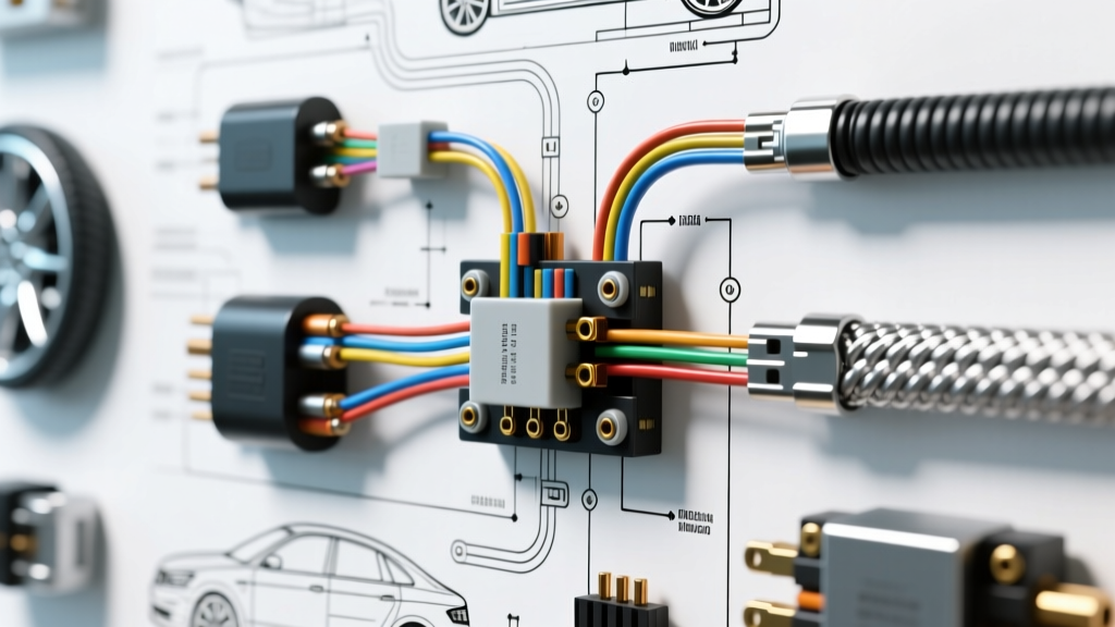
Introduction: Why Wire Gauge Mismatches Cause Electrical Failures
Electrical faults in modern and classic vehicles frequently trace back to a fundamental mismatch between circuit load and wire capacity. When an aftermarket accessory, a failing factory component, or an incorrect repair draws more current than the wiring harness can safely carry, the result is excessive heat, severe voltage drop, and eventually, melted connectors or harness fires. To diagnose these issues systematically, master technicians rely on an american wire gauge amp chart to verify if the physical wire size matches the electrical demand of the circuit.
Unlike residential AC wiring, automotive DC electrical systems operate at a nominal 12.6V to 14.4V, meaning they require significantly higher amperage to deliver the same wattage. A 1200W car audio amplifier, for example, will draw over 100 amps at 12 volts. If the installer uses an undersized wire, the resistance of the cable will generate massive heat. This troubleshooting flow is designed to help you identify, test, and resolve gauge-related electrical failures using precise measurements and industry-standard reference data.
The Core Reference: American Wire Gauge Amp Chart for Automotive DC
Before beginning any diagnostic flow, you must understand the baseline limits of the conductors you are testing. The following american wire gauge amp chart is based on SAE J1128 standards for low-tension primary cable, which accounts for the high-temperature environment of an engine bay. Note that these ampacity ratings are for single conductors in free air or standard chassis wiring; bundling multiple wires together in a tight loom reduces heat dissipation and requires derating the maximum amperage.
| AWG Size | Max Amps (Chassis) | Resistance (Ohms per 10ft) | Common Automotive Application |
|---|---|---|---|
| 18 AWG | 6A | 0.0638 | Dash illumination, ECU sensor grounds, LED markers |
| 16 AWG | 10A | 0.0401 | Tail lights, interior dome lights, horn relay trigger |
| 14 AWG | 15A | 0.0252 | Fuel pump feed, power seat switches, cigarette lighter |
| 12 AWG | 20A | 0.0159 | Headlight low beam, power windows, ABS module power |
| 10 AWG | 30A | 0.0100 | Ignition main feed, radiator fan primary relay feed |
| 8 AWG | 40A | 0.0062 | Rear defroster, trailer brake controller power feed |
| 4 AWG | 80A | 0.0002 | Standard alternator B+ to battery, main starter feed |
| 1/0 AWG | 150A | 0.0001 | High-output alternator upgrades, EV battery interconnects |
Step-by-Step Troubleshooting Flow: Diagnosing Gauge-Related Failures
When a customer complains of dimming headlights, a dead battery, or a melted fuse block, follow this sequential diagnostic tree to isolate wire gauge and resistance faults.
Step 1: Identify the Symptom and Calculate Circuit Load
Begin by identifying the exact failure mode. Thermal damage (blistered insulation, deformed nylon connectors) indicates continuous overloading or high resistance. Voltage drop symptoms (dimming lights, slow cranking, ECU low-voltage DTCs like P0562) indicate undersized wiring or poor terminations.
Calculate the total expected amperage of the circuit. For example, if a circuit powers two 55W H11 halogen low-beam bulbs, the total wattage is 110W. Using Ohm's Law (Amps = Watts / Volts), 110W / 12.6V = 8.73 Amps. According to the american wire gauge amp chart, a 16 AWG wire (rated for 10A) is technically sufficient, but a 14 AWG wire is preferred to account for voltage drop over long harness runs and inrush current surges.
Step 2: Measure Actual Current Draw vs. Wire Capacity
Never rely solely on the fuse size to determine wire capacity; previous owners or mechanics may have installed an oversized fuse to stop a blown circuit, masking a severe fire hazard. Use a DC clamp meter around the positive wire feeding the load.
- Normal Operation: Current draw is within 10% of the calculated load and below the AWG rating.
- Overload Condition: Current draw exceeds the AWG rating. This requires upsizing the wire and upgrading the fuse to match the new wire capacity.
- Short to Ground: Current draw instantly spikes to the maximum output of the power source, blowing the fuse. This is a physical insulation failure, not necessarily a gauge sizing issue.
Step 3: Perform a Voltage Drop Test Under Load
This is the most critical step in the troubleshooting flow. A wire might be the correct gauge, but poor crimps, corrosion, or undersized terminals will create resistance, mimicking the symptoms of a wire that is too small. Set your Digital Multimeter (DMM) to the DC millivolt (mV) scale.
- Connect the DMM red probe to the positive battery post and the black probe to the positive terminal of the load (e.g., the starter motor B+ post).
- Activate the circuit or crank the engine. The circuit MUST be under load to push current through the resistance.
- Read the voltage drop. According to Painless Performance Wiring guidelines, a high-amperage circuit (like a starter or alternator feed) should have a maximum voltage drop of 0.10V (100mV) per connection, and no more than 0.20V total for the entire positive cable run.
- If the drop exceeds 0.20V on a 4 AWG cable drawing 80A, the cable is either too long, severely corroded internally, or made of inferior conductive material.
Step 4: Inspect for Thermal Damage and Connector Melt
If the voltage drop test indicates high resistance at a specific junction, physically inspect the connector. Automotive connectors like the Delphi Weather-Pack and Metri-Pack 280 series use nylon housings with a melting point around 220°C. If the wire gauge is too small for the amperage, the copper strands will act as a heating element. This heat travels down the wire via conduction and melts the connector housing from the inside out, causing the female terminal to lose its spring tension. This creates a micro-gap, leading to electrical arcing and total connector failure.
Real-World Case Study: Upgrading a 150A Alternator Charge Wire
A common scenario in the restoration and off-road community is upgrading a factory 90A alternator to a 150A high-output unit, such as those used in police interceptors or heavy-duty trucks. Consider a 1998 Chevrolet Silverado with a factory 8 AWG alternator charge wire routed to the main battery.
According to our american wire gauge amp chart, 8 AWG wire is only rated for roughly 40A to 50A in continuous chassis wiring applications. Pushing 120A of continuous charging current through an 8 AWG wire that is 6 feet long will result in a massive voltage drop and severe heat generation. The factory insulation will blister, and the alternator will fail to keep the battery charged at idle because the voltage at the battery post is too low.
The Fix: The correct troubleshooting resolution is to replace the entire positive charge wire with 2 AWG Oxygen-Free Copper (OFC) fine-strand welding cable. The technician must crimp 5/16-inch closed-end ring terminals using a ratcheting hex-crimp tool, apply marine-grade adhesive heat shrink to seal out moisture, and torque the alternator B+ terminal nut to exactly 110 in-lbs to ensure maximum surface contact area. After the upgrade, a voltage drop test under heavy electrical load should read less than 0.05V across the entire new 2 AWG cable.
Common Wiring Mistakes and Failure Modes
When using an american wire gauge amp chart to spec out a repair or modification, avoid these critical errors that compromise the integrity of the electrical system:
- Using CCA (Copper-Clad Aluminum) Wire: Many cheap aftermarket wire kits use CCA instead of pure OFC copper. Aluminum has roughly 60% of the conductivity of copper. A 4 AWG CCA wire will perform electrically like a 6 AWG pure copper wire, leading to unexpected voltage drops and overheating. Always slice the wire end to verify the core is solid copper, not silver-colored aluminum.
- Incorrect Stranding for Automotive Use: Residential solid-core wire and coarse-strand building wire (THHN) are not designed for the constant vibration of a vehicle chassis. Vibration causes solid-core wire to work-harden, snap, and short out. Always use SAE J1128 compliant fine-strand or extra-fine-strand primary automotive wire.
- Soldering High-Amp Connections: While soldering is fine for low-amperage sensor wires (18-20 AWG), it should never be used for high-amperage battery or alternator cables. Solder has a much lower melting point than copper and will flow out of the joint under high thermal loads, leading to a catastrophic open circuit. Always use mechanical, ratcheting crimps for wires 8 AWG and larger.
By strictly adhering to the specifications outlined in an american wire gauge amp chart and following this systematic troubleshooting flow, you can eliminate guesswork, prevent electrical fires, and ensure that every circuit in the vehicle operates at peak efficiency. For further reading on automotive wire standards, refer to the National Electrical Code (NEC) Chapter 9 Table 8 for baseline copper resistance metrics, while prioritizing SAE standards for under-hood temperature derating.