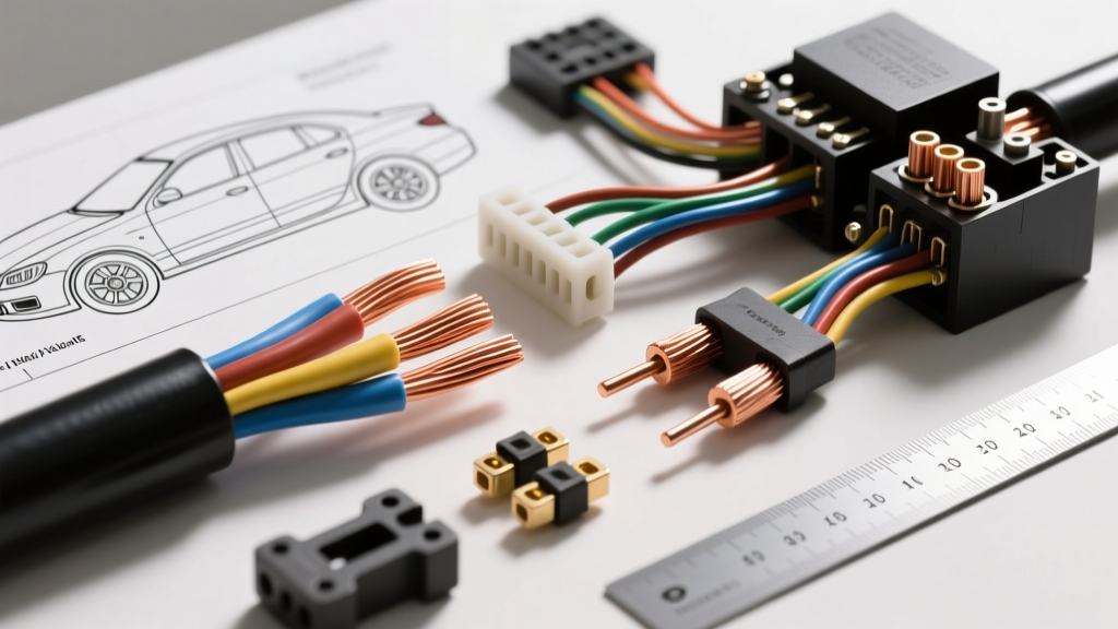
The Core Definition of Wire Gauge in Automotive Systems
At its most fundamental level, the definition of wire gauge refers to the standardized measurement of the physical diameter and cross-sectional area of an electrical conductor. In the automotive and North American electrical industries, this is predominantly defined by the American Wire Gauge (AWG) system, originally based on the Brown & Sharpe wire drawing standard. The AWG system operates on an inverse logarithmic scale: the smaller the gauge number, the larger the physical diameter of the wire and the greater its current-carrying capacity (ampacity).
Understanding this definition is critical for automotive applications because 12-volt and 24-volt DC electrical systems demand significantly higher amperage to deliver the same wattage as standard 120V AC household systems. According to Ohm's Law (Current = Power / Voltage), a 100-watt headlight on a 120V home circuit draws less than 1 ampere. That same 100-watt headlight in a 12V vehicle draws over 8.3 amperes. If the wire gauge is undersized, the inherent resistance of the copper generates excess heat and causes a voltage drop, leading to dim lighting, ECU sensor faults, or in extreme cases, an engine bay fire.
AWG vs. Metric Sizing: Cross-Sectional Area Standards
While North American manufacturers rely on AWG, European and Asian automotive platforms (such as BMW, Volkswagen, and Toyota) frequently utilize the metric standard, measured in square millimeters (mm²). When performing cross-platform swaps or integrating aftermarket CAN-bus modules, technicians must translate the definition of wire gauge from AWG to metric to maintain proper circuit resistance.
| AWG Size | Metric (mm²) | Cross-Sectional Area | Max Amps (Chassis) | Resistance per 1,000 ft (Copper) | Common Automotive Application |
|---|---|---|---|---|---|
| 20 AWG | 0.50 mm² | 0.518 mm² | 5A | 10.15 Ω | ECU Sensor Signals, Injector Pulses |
| 18 AWG | 0.75 mm² | 0.823 mm² | 7A | 6.38 Ω | Dashboard Illumination, Low-Draw Relays |
| 16 AWG | 1.00 mm² | 1.310 mm² | 10A | 4.01 Ω | Tail Lights, Horns, O2 Sensor Heaters |
| 14 AWG | 1.50 mm² | 2.080 mm² | 15A | 2.52 Ω | Headlights, Fuel Pumps, Power Windows |
| 12 AWG | 2.50 mm² | 3.310 mm² | 20A | 1.58 Ω | Cigar Lighter, Blower Motor, ABS Modules |
| 10 AWG | 4.00 mm² | 5.260 mm² | 30A | 0.99 Ω | Ignition Feeds, High-Current Solenoids |
| 8 AWG | 6.00 mm² | 8.370 mm² | 45A | 0.62 Ω | Amplifier Power, Electric Fan Relays |
| 4 AWG | 16.00 mm² | 21.15 mm² | 70A | 0.24 Ω | Alternator to Battery, Starter Motor |
Conductor Material Comparison: OFC vs. CCA
When evaluating products based on the definition of wire gauge, the material composition is just as critical as the physical diameter. The automotive aftermarket is flooded with two primary conductor types: Oxygen-Free Copper (OFC) and Copper-Clad Aluminum (CCA).
Oxygen-Free Copper (OFC)
OFC is the gold standard for automotive wiring. It offers 100% copper conductivity, high tensile strength, and excellent resistance to the continuous micro-vibrations inherent in internal combustion engines. OFC wire maintains its structural integrity when crimped into open-barrel terminals and resists galvanic corrosion when exposed to road salt and moisture.
Copper-Clad Aluminum (CCA)
CCA wire features an aluminum core electroplated with a thin layer of copper. While it is cheaper and lighter, aluminum has roughly 60% higher electrical resistance than copper. To achieve the same ampacity as a 10 AWG OFC wire, you would need a significantly thicker CCA wire. Furthermore, aluminum suffers from 'cold flow' under pressure, meaning crimped connections can loosen over time due to engine vibration, leading to arcing and melted connectors. CCA should be strictly avoided in engine bay and high-current chassis applications.
Automotive Insulation Grades: SAE J1128 Standards
The definition of wire gauge only accounts for the conductor. In automotive environments, the insulation jacket dictates the wire's survivability. The SAE J1128 Low Tension Primary Cable Standard governs the chemical and thermal requirements for automotive wire insulation. Unlike household THHN wire, which uses brittle PVC that melts on contact with exhaust manifolds and degrades when exposed to engine oil, automotive wire uses Cross-Linked Polyethylene (XLPE).
- GXL (General Cross-Linked): Thin-wall insulation. Highly resistant to heat (up to 125°C) and chemicals. The standard choice for modern engine bay wiring harnesses where space is at a premium.
- TXL (Thin Cross-Linked): Extra thin-wall insulation. Rated for 125°C. Used extensively by OEMs in tight cabin looms and dashboard harnesses to reduce overall harness weight and diameter.
- SXL (Standard Cross-Linked): Thicker wall insulation. Rated for 125°C. Offers superior abrasion resistance for routing through sheet metal firewalls and undercarriage chassis runs where road debris impact is a factor.
Circuit-Specific Wire Selection Matrix
Selecting the correct gauge requires analyzing both the continuous amperage draw and the acceptable voltage drop threshold of the specific component. Critical ECU sensors require minimal voltage drop, whereas resistive heating elements can tolerate slightly higher resistance.
1. Wideband O2 Sensors (e.g., Bosch LSU 4.9)
Wideband sensors utilize a 6-pin connector. The signal circuit (Pins 1 and 2, typically White and Black wires) carries millivolt-level analog data to the ECU. This requires 20 AWG shielded twisted pair wire to prevent electromagnetic interference (EMI) from the alternator. The internal ceramic heater circuit (Pins 3 and 4, Gray wires) draws between 2A and 8A on cold start. Using 18 AWG wire for the heater circuit will result in a voltage drop, causing the sensor to take too long to reach closed-loop operation. Always use 16 AWG GXL for the O2 heater ground and power feeds.
2. High-Current Fuel Pumps (e.g., Walbro 450 / AEM 340)
Upgraded in-tank fuel pumps can draw 15A to 25A continuously under high boost. The factory wiring is often 16 AWG, which is dangerously undersized for aftermarket pumps. Upgrading the feed and ground lines to 12 AWG OFC ensures the pump receives a full 13.5V to 14.2V, maximizing flow rate and preventing the factory harness from melting at the bulkhead connector.
3. Starter and Alternator Upgrades
When upgrading to a 200-amp alternator for high-draw audio systems, the factory 8 AWG or 6 AWG wire will act as a bottleneck. Upgrade the alternator output to the main battery terminal using 1/0 AWG OFC welding cable. Terminate with heavy-duty copper ring lugs, crimped using a hex-pattern hydraulic die to ensure zero air gaps in the copper strands.
Real-World Failure Modes from Incorrect Gauge Selection
Misunderstanding the definition of wire gauge and selecting undersized products leads to predictable, yet often misdiagnosed, failure modes:
- ECU Sensor Resets: If a 5V reference wire from the ECU to a MAP sensor is routed using a damaged or undersized 22 AWG wire, the resistance will drop the voltage to 4.6V. The ECU will log a 'Sensor Circuit Low' code, even if the sensor itself is perfectly functional.
- Headlight Dimming & Relay Chatter: Running 16 AWG wire to a pair of 55W H7 headlight bulbs causes a 1.5V drop. The lights appear yellow and dim. Furthermore, the voltage drop at the relay coil can cause it to rapidly open and close (chatter), burning out the relay contacts.
- Alternator Whine in Audio: Using CCA wire instead of OFC for amplifier power grounds introduces fluctuating resistance. As the engine RPM changes, the alternator's AC ripple leaks into the audio ground path, resulting in a high-pitched whine through the speakers.
For comprehensive connector and terminal specifications, technicians should refer to the TE Connectivity Automotive Electrical Standards documentation, which outlines the precise crimp heights and pull-test requirements for matching specific wire gauges to their proprietary open-barrel terminals. Proper wire selection is not just about preventing fires; it is about ensuring the precise voltage delivery required by modern, computer-controlled vehicle systems.