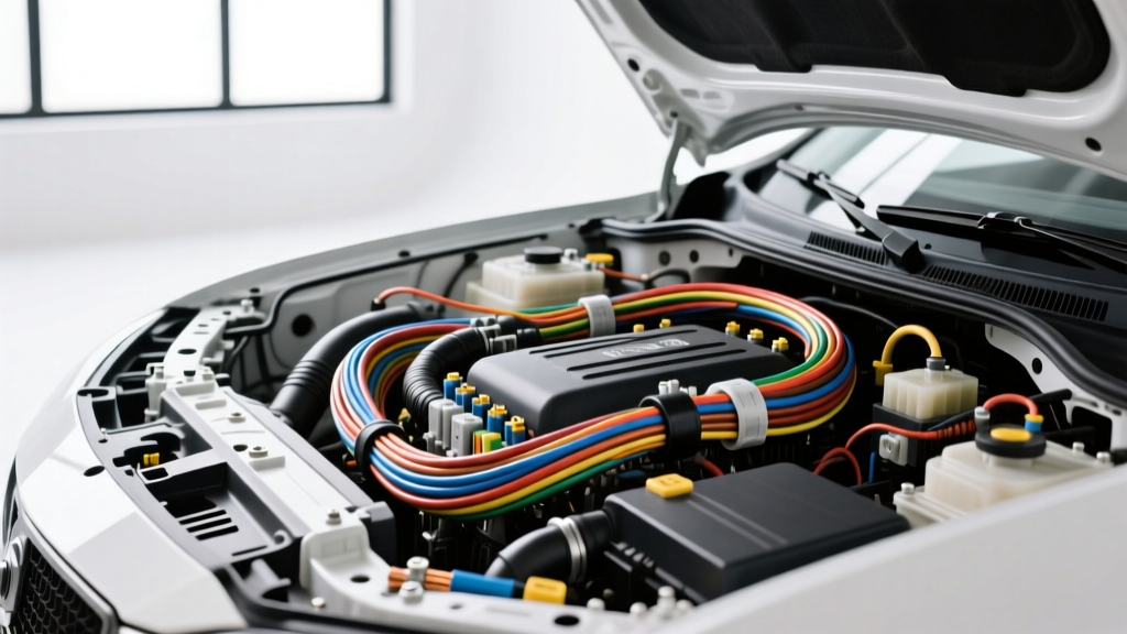
Defining Heavy Gauge Wire in Automotive Applications
When executing high-draw automotive modifications—such as installing a 250-amp high-output alternator, integrating a 12,000 lb winch, or building a dual-battery overland system—factory wiring harnesses become the primary bottleneck. In automotive electrical engineering, heavy gauge wire typically refers to conductors sized between 4 AWG and 4/0 AWG (American Wire Gauge). These massive conductors are required to handle continuous loads exceeding 100 amps and peak transient loads surpassing 600 amps without suffering from catastrophic voltage drop or thermal runaway.
Unlike standard chassis wiring, which relies on thin PVC insulation and coarse stranding, heavy gauge wire used in aftermarket upgrades must meet rigorous flexibility and thermal resistance standards. Selecting the incorrect wire gauge or insulation type for a high-amp modification will result in dimming headlights, slow winch recovery speeds, and potentially melted insulation leading to chassis short circuits.
Heavy Gauge Wire Specification & Ampacity Chart
The following reference chart outlines the critical specifications for heavy gauge wire commonly used in automotive and marine high-amp upgrades. Ampacity ratings are based on SAE J1128 standards for single conductors in free air (chassis wiring) with an ambient temperature of 30°C (86°F). Always apply a 20% derating factor for wire routed through enclosed engine bay looms or high-heat zones near exhaust manifolds.
| AWG Size | Metric (mm²) | Strand Count (Class K) | Max Amps (Chassis) | Ohms per 1,000 ft | Weight (lbs/1k ft) |
|---|---|---|---|---|---|
| 4 AWG | 21.1 mm² | 1,330 | 125A | 0.2485 Ω | 124 lbs |
| 2 AWG | 33.6 mm² | 2,107 | 175A | 0.1563 Ω | 198 lbs |
| 1 AWG | 42.4 mm² | 2,646 | 215A | 0.1239 Ω | 250 lbs |
| 1/0 AWG | 53.5 mm² | 3,321 | 260A | 0.0983 Ω | 315 lbs |
| 2/0 AWG | 67.4 mm² | 4,186 | 300A | 0.0779 Ω | 397 lbs |
Note: For continuous duty applications like high-output alternator charging circuits, 1/0 AWG is the industry standard baseline to ensure minimal voltage drop across the 10-to-15 foot round-trip circuit length.
Stranding Classes: Why Fine Strand Matters for Mods
Not all heavy gauge wire is manufactured equally. When sourcing cable for vehicle modifications, you must pay attention to the stranding class. Standard battery cable often uses coarse Class B stranding, which is stiff and prone to work-hardening and fracturing under the constant vibration of a vehicle chassis or diesel engine.
- Class K (Standard Fine): Uses 30 AWG individual copper strands. Highly flexible and the standard for premium aftermarket welding cable and marine-grade battery wire.
- Class M (Extra Fine): Uses 34 AWG individual strands. Extremely flexible, often used in tight-radius routing scenarios, but the individual strands are more delicate and require careful handling during the crimping process to avoid shearing.
For 95% of automotive upgrades, Class K stranding offers the optimal balance of flexibility, vibration resistance, and ease of termination.
Application Guide: High-Amp Modification Projects
The 'Big 3' Alternator and Ground Upgrade
The 'Big 3' upgrade involves replacing or supplementing the three main factory power and ground cables with heavy gauge wire (typically 1/0 AWG). This mod is mandatory when upgrading to a 200A+ alternator to power massive car audio amplifiers or off-road LED light bars.
- Alternator B+ to Battery Positive: Use 1/0 AWG red wire. Factory wires are often 4 AWG or smaller and bottleneck the new alternator's output. Route the new wire away from exhaust headers and steering shafts.
- Battery Negative to Chassis Ground: Use 1/0 AWG black wire. Locate a clean, unpainted, threaded chassis point. Use a 3/8' (M10) ring terminal and torque to 25-30 lb-ft.
- Engine Block to Chassis Ground: The engine rests on rubber isolators, meaning the alternator's ground return path relies entirely on this strap. Use 1/0 AWG black wire, attaching to a dedicated cast-iron boss on the engine block.
High-Draw Winch and Power Distribution Wiring
A 12,000 lb electric winch can draw upwards of 450 amps under maximum stall load. Using undersized wire here will result in severe voltage drop, causing the winch motor to overheat and the solenoid contacts to weld shut.
For winch installs, use 2 AWG or 1/0 AWG welding cable. Because winch circuits are only active for short durations (intermittent duty), 2 AWG is often sufficient for runs under 6 feet. However, if you are routing power to a rear-mounted receiver hitch winch plate (requiring a 20+ foot cable run), you must step up to 1/0 AWG or 2/0 AWG to compensate for the increased resistance over distance. Always terminate winch circuits using a heavy-duty solenoid contactor (e.g., Trombetta or Cole Hersee 250A continuous relays) rather than routing heavy gauge wire directly into the cabin to a dashboard switch.
Calculating Voltage Drop in Heavy Gauge Circuits
Voltage drop is the silent killer of high-amp automotive modifications. Even heavy gauge wire has resistance. If the voltage at your high-output alternator is 14.4V, but the voltage at the battery post is 13.2V due to wire resistance, your battery will never reach full state-of-charge, and your BMS (Battery Management System) will throttle the alternator.
The Voltage Drop Formula:
VD = (2 x L x I x R) / 1000
Where: L = One-way length in feet, I = Current in Amps, R = Resistance per 1,000 ft of wire.
Example: Upgrading to a 220A alternator using 1/0 AWG wire (0.0983 Ω/1000ft) with a 5-foot one-way run (10 feet round trip).
VD = (10 x 220 x 0.0983) / 1000 = 0.216 Volts.
A drop of 0.216V is well within the acceptable SAE limit (under 3% of system voltage, which is 0.43V for a 14.4V system). If you used 4 AWG wire for this same 220A load, the drop would be 0.546V, causing severe charging system inefficiencies.
Termination Protocols and Common Failure Modes
The most common point of failure in any heavy gauge wire modification is not the wire itself, but the termination. A poorly crimped 1/0 AWG ring terminal will introduce micro-ohms of resistance, generating massive heat under load.
Proper Crimping Techniques
Never use hammer-style crimpers or pliers on wire larger than 4 AWG. For 1/0 AWG and larger, you must use a hydraulic hex-indent crimper (minimum 6-ton pressure). The hex-indent die compresses the copper strands and the terminal barrel into a solid, void-free mass, effectively cold-welding them together. This reduces the internal void ratio, preventing moisture ingress and galvanic corrosion.
Sealing and Heat Shrink
After crimping, always seal the termination using 3:1 ratio, adhesive-lined dual-wall heat shrink tubing. When heated, the inner wall melts and flows into the wire strands, creating a waterproof environmental seal that prevents capillary action from drawing battery acid or road salt under the insulation.
Torque Specifications and Hardware
Heavy gauge wire requires precise torque to maintain low-resistance connections without snapping the hardware.
- Alternator B+ Terminal (M8 Nut): 15 - 18 lb-ft. Over-torquing will snap the alternator output stud, destroying the diode bridge.
- GM Side-Post Battery Terminals: 10 - 12 lb-ft. Highly susceptible to cross-threading and stripping. Use stainless steel bolts with a copper anti-seize compound.
- Standard Top-Post Battery Clamps: Ensure the heavy gauge ring terminal (usually 3/8' or 5/16') is placed directly against the lead post, with the factory clamp securing it from the top. Never stack multiple heavy gauge ring terminals on a single standard battery stud without using a dedicated copper busbar or power distribution block.
Authoritative References
For further engineering data on automotive cable standards and high-amp modification protocols, consult the following resources:
- SAE J1128: Low Tension Primary Cable - Society of Automotive Engineers standard covering physical dimensions, thermal ratings, and insulation requirements for automotive wiring.
- MAD Enterprises: The Big 3 Upgrade Guide - Comprehensive technical documentation on alternator and ground circuit upgrades for high-draw vehicle systems.
- Pacer Group Technical Resources - Detailed reference charts for wire stranding classes, AWG to metric conversions, and marine-grade heavy gauge wire specifications.