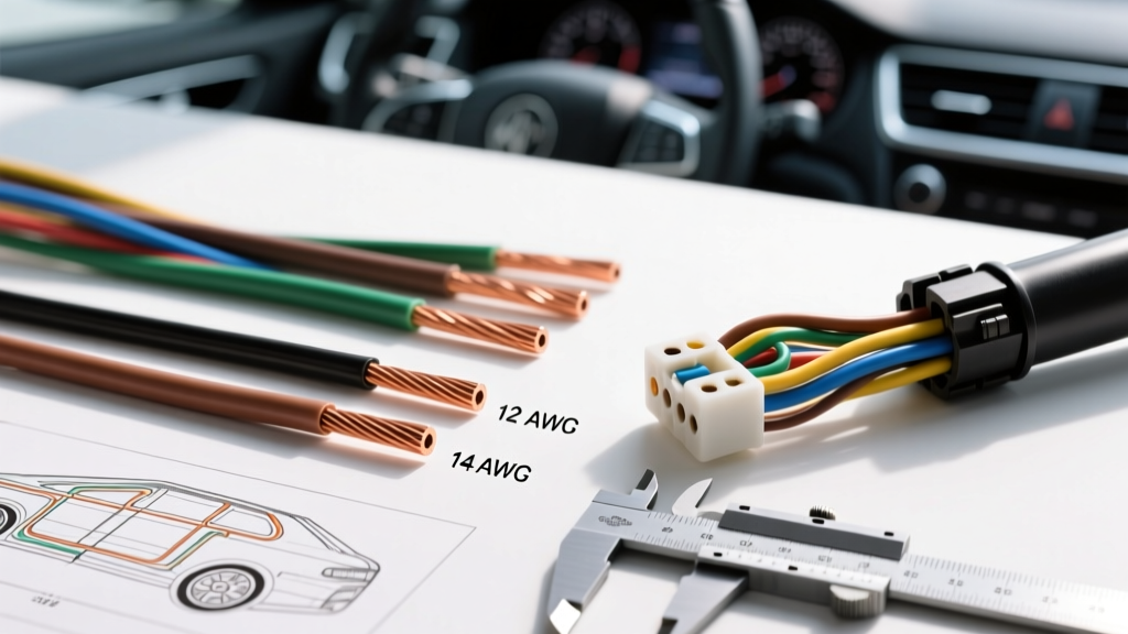
The Short Answer: Is 12 Gauge Wire Thicker Than 14?
If you are staring at two spools of automotive primary wire and asking, "is 12 gauge wire thicker than 14?", the definitive answer is yes. In the American Wire Gauge (AWG) system, the physical diameter of the conductor increases as the gauge number decreases. Therefore, 12 AWG wire is significantly thicker, heavier, and capable of carrying more electrical current than 14 AWG wire.
Understanding this counterintuitive sizing scale is critical for automotive electricians and DIY enthusiasts. Using a wire that is too thin for a specific circuit results in excessive voltage drop, melted insulation, and potentially catastrophic electrical fires. This practical installation guide will break down the exact specifications of 12 AWG versus 14 AWG wire, outline their specific automotive use cases, and provide a step-by-step tutorial for upgrading a high-draw accessory circuit using proper SAE standards.
Understanding the AWG (American Wire Gauge) Scale
The AWG system was established in 1857 and is based on the manufacturing process of wire drawing. To reduce a thick copper rod down to a specific wire size, it is pulled through a series of progressively smaller drawing dies. A 14 AWG wire has been pulled through more dies than a 12 AWG wire, resulting in a smaller final diameter. Because automotive electrical systems operate on a 12V to 14.4V DC architecture, current (Amperage) requirements are exceptionally high compared to 120V/240V AC household systems. According to SAE International J1128 standards for low-tension automotive cable, selecting the correct gauge is dictated by the maximum continuous amperage draw and the total length of the circuit to prevent voltage drop exceeding 3%.
Technical Specifications: 12 AWG vs. 14 AWG Automotive Wire
Automotive wire is typically manufactured with cross-linked polyethylene insulation (GXL or TXL), which allows for higher temperature tolerances and thinner insulation walls compared to standard PVC wire. This affects the overall outer diameter (OD) while maintaining the copper cross-section. Below is the comparative specification chart for standard copper automotive wire.
| Specification | 14 AWG (GXL) | 12 AWG (GXL) |
|---|---|---|
| Strand Count (Typical) | 41 x 0.254mm | 65 x 0.254mm |
| Nominal Copper Diameter | 0.0641 inches (1.63mm) | 0.0808 inches (2.05mm) |
| Cross-Sectional Area | 2.08 mm² | 3.31 mm² |
| Resistance @ 20°C (Ω/1000ft) | 2.52 Ω | 1.59 Ω |
| Max Ampacity (Single Wire, Free Air) | 32 Amps | 41 Amps |
| Typical Insulation OD | 0.092 inches | 0.115 inches |
Note: Ampacity ratings drop significantly when wires are bundled in loom or conduit due to trapped thermal energy. Always apply a 20% derating factor for bundled harnesses.
Practical Application: Selecting the Right Gauge for Your Build
When to Deploy 14 AWG Wire
14 AWG wire is the workhorse for low-to-medium draw circuits where flexibility and weight savings are prioritized. It is perfectly suited for:
- LED Lighting Upgrades: Aftermarket LED light bars or fog lights drawing under 10A total.
- Interior Accessories: Powering glovebox lights, USB charging modules, or low-draw gauge clusters.
- Sensor Pigtails: Fabricating repair harnesses for O2 sensors, MAP sensors, or TPS switches where high current is not present.
- Relay Trigger Circuits: Wiring the 85 and 86 pins on a standard Bosch-style automotive relay, which only carry the low-amperage switching current from the cabin switch or ECU.
When to Step Up to 12 AWG Wire
When a circuit exceeds 15A of continuous draw, or when the wire run exceeds 15 feet from the power source to the load, 12 AWG is required to mitigate voltage drop. Common applications include:
- Main Power Feeds: Supplying 12V+ to aftermarket fuse blocks or relay centers from the battery.
- High-Draw Lighting: Halogen or HID headlight power feeds (where inrush current can spike significantly).
- Fuel Pumps: In-tank or inline high-pressure fuel pumps (e.g., Walbro 255lph or DeatschWerks DW300c) which require steady voltage to maintain flow rate.
- Cooling Fans: Primary radiator puller fans which can draw 20A-25A under peak load.
Step-by-Step Installation: Upgrading Headlight Power Feed (12 AWG)
A common failure mode in older vehicles (such as the 1990-1997 Mazda Miata or 1988-1998 Chevy Silverado) is the factory headlight wiring relying on 16 or 14 AWG wire routed through the steering column switch. This causes severe voltage drop, resulting in dim lights and melted switches. Here is how to install a 12 AWG relay bypass harness.
Materials and Tooling Required
- 12 AWG GXL Wire (Red for 12V+, Black for Ground)
- 14 AWG GXL Wire (Blue for trigger signal)
- Bosch-style 5-pin SPDT Relay (Pins: 30, 87, 86, 85)
- Aptiv Metri-Pack 630 Series female terminals (for 12 AWG high-current pins 30 and 87)
- Metri-Pack 280 Series female terminals (for 14 AWG trigger pins 85 and 86)
- Adhesive-lined dual-wall heat shrink (3/16" and 1/4" sizes)
- Ratchet-style crimping tool with specific Metri-Pack die profiles
Execution Steps
- Prepare the Power Feed (Pin 30): Cut a length of 12 AWG Red wire to reach from the positive battery terminal to the relay location. Strip 5mm of insulation. Crimp a Metri-Pack 630 terminal using the ratchet crimper. The crimp must pass the 'tug test' and show the wire strands flush with the terminal bellmouth. Seal with 1/4" adhesive heat shrink.
- Prepare the Load Feed (Pin 87): Cut 12 AWG Red wire to run from Pin 87 to the headlight positive feed. Terminate with a Metri-Pack 630 on the relay side, and the appropriate OEM-style connector (e.g., H4 ceramic plug) on the headlight side.
- Wire the Trigger Circuit (Pin 86): Use 14 AWG Blue wire. Tap into the factory headlight positive wire using a solder-seal butt connector. Terminate the relay side with a Metri-Pack 280 terminal.
- Establish Ground (Pin 85): Use 14 AWG Black wire. Terminate with a Metri-Pack 280 on the relay side, and a 10-12 AWG ring terminal (#10 stud hole) on the chassis side. Ensure the chassis grounding point is sanded to bare metal and treated with dielectric grease to prevent oxidation.
- Secure and Loom: Wrap the entire harness in Tesa cloth friction tape to prevent rattling and abrasion against the firewall or radiator support. Secure with UV-resistant zip ties every 8 inches.
Troubleshooting Voltage Drop and Thermal Failures
Even if you correctly identify that 12 gauge wire is thicker than 14, improper installation can negate the benefits of the larger conductor. Use this diagnostic matrix to identify common wiring faults:
| Symptom | Probable Cause | Corrective Action |
|---|---|---|
| Wire feels hot to the touch under load | Undersized wire for the run length, or high resistance at a crimp joint. | Verify voltage drop across the wire using a multimeter. If drop > 0.3V, upgrade to 10 AWG or re-crimp terminals. |
| Terminal pushes out of connector cavity | Incorrect terminal series used (e.g., forcing 12 AWG wire into a 280 series cavity). | Use 630 series terminals for 12 AWG high-current applications. Ensure the secondary lock (TPA) is fully seated. |
| Insulation melts near the terminal crimp | Stray wire strands causing a short, or high resistance due to a non-ratchet crimp tool. | Cut back wire, strip cleanly, and use a calibrated ratchet crimper. Never use pliers for automotive terminals. |
Conclusion
When planning an automotive electrical project, remembering that 12 gauge wire is thicker than 14 gauge is just the starting point. True reliability comes from matching the SAE J1128 ampacity ratings to your specific load, accounting for voltage drop over distance, and utilizing professional-grade crimping techniques. By selecting the correct gauge and following proper installation protocols, you ensure your vehicle's electrical system remains safe, efficient, and capable of handling the demands of modern aftermarket accessories.
For further reading on automotive wiring standards, consult the Painless Performance Wiring Manual for comprehensive chassis routing and circuit protection guidelines.