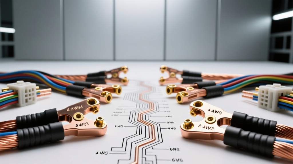
The Metallurgy of a Perfect Copper Wire Splice
In high-current automotive applications—ranging from EV battery interconnects and winch solenoids to high-output alternator upgrades—the integrity of a copper wire splice dictates the survival of the entire circuit. A poorly executed splice on an 8 AWG or 4 AWG circuit carrying 60 to 120 amps will rapidly succumb to thermal runaway. To understand why, we must examine the metallurgy of the conductor itself.
Most automotive primary wire adhering to SAE J1128 standards utilizes Electrolytic Tough Pitch (ETP) copper (C11000), which is 99.9% pure. However, bare copper is highly susceptible to oxidation. Copper oxide is a semiconductor; as the oxide layer builds up at the interface of a wire-to-terminal splice, electrical resistance increases. This resistance generates heat (I²R losses), which accelerates further oxidation in a destructive feedback loop.
To combat this, premium automotive copper wire and splice terminals are tin-plated. The tin acts as a sacrificial barrier against galvanic corrosion and oxygen ingress. When executing a copper wire splice, it is critical to use tin-plated copper barrels rather than bare brass or aluminum alternatives, which introduce dissimilar metal galvanic corrosion when exposed to road salt and engine bay moisture.
The Physics of Cold Welding: Crimp vs. Solder
A persistent myth in garage wiring is that soldering a copper wire splice provides a superior electrical connection. From an advanced engineering perspective, soldering is actively detrimental in high-vibration, high-thermal-cycling automotive environments. Solder (typically a tin-lead or tin-copper alloy) melts at approximately 183°C to 227°C. Under heavy continuous loads, such as an electric cooling fan drawing 45 amps through a 10 AWG wire, the ambient under-hood temperature combined with I²R heating can cause the solder to soften, leading to creep and eventual mechanical failure.
Furthermore, solder wicks into the copper strands via capillary action, creating a rigid section of wire immediately adjacent to the splice. In a high-vibration environment (like a chassis-mounted winch relay), this rigid-to-flexible transition point becomes a stress concentrator, leading to copper strand fatigue and breakage. Reference NASA-STD-8739.4 workmanship standards, which mandate crimping over soldering for high-reliability connections due to the superior mechanical retention and gas-tight seal achieved through cold welding.
A properly calibrated crimp deforms the copper wire and the terminal barrel simultaneously, breaking through the tin oxide layers and forcing raw copper-to-copper contact. The immense pressure creates a gas-tight cold weld that is entirely impervious to oxygen and moisture, while maintaining the mechanical flexibility of the copper strands.
AWG to Terminal Barrel Sizing Matrix
Selecting the correct splice barrel internal diameter (ID) relative to the copper wire's outer diameter (OD) is non-negotiable. An oversized barrel will result in an incomplete crimp with void spaces, while an undersized barrel will shear the copper strands during compression. The following matrix outlines the exact specifications for heavy-gauge automotive copper wire splices using hex-crimp terminals.
| Wire Gauge (AWG) | Strand Count & OD (in) | Splice Barrel ID (in) | Hex Crimp Die Size (in) | Min. Pull-Out Force (lbs) |
|---|---|---|---|---|
| 4 AWG | 133 / 0.232 | 0.245 - 0.255 | 0.210 (Red/Black) | 350 |
| 6 AWG | 133 / 0.184 | 0.195 - 0.205 | 0.160 (Blue) | 250 |
| 8 AWG | 133 / 0.146 | 0.155 - 0.165 | 0.130 (Yellow) | 150 |
| 10 AWG | 37 / 0.115 | 0.120 - 0.130 | 0.105 (Green) | 90 |
| 12 AWG | 19 / 0.092 | 0.095 - 0.105 | 0.085 (Orange) | 60 |
Note: Always verify terminal specifications with the manufacturer, as barrel IDs can vary slightly between stamped butt splices and machined hex-crimp splices.
Step-by-Step High-Current Splice Execution
For circuits exceeding 30 amps, standard nylon-insulated vinyl crimps are insufficient. You must utilize bare copper heavy-duty splice barrels enclosed in dual-wall, polyamide-lined heat shrink. Follow this exact sequence for a 4 AWG to 8 AWG step-down copper wire splice, commonly found in aftermarket winch installations or high-amperage inverter feeds.
1. Precision Stripping and Inspection
Use a calibrated rotary wire stripper set specifically for the AWG size. The goal is to remove the cross-linked polyethylene (XLPE) or PVC insulation without nicking the outer copper strands. A nicked strand reduces the cross-sectional area and creates a localized hot spot. The strip length must precisely match the barrel depth, allowing for exactly 1mm of wire protrusion on the mating side to verify full insertion.
2. The Crimp Sequence
Insert the 4 AWG wire into the larger barrel end and the 8 AWG wire into the smaller end. Using a pneumatic or ratcheting hex-crimp tool, position the wire so the insulation gap is perfectly centered in the tool's nest. Squeeze the tool until the ratchet releases. The resulting hex crimp should exhibit a slight "bellmouth" at the wire entry and exit points, ensuring no sharp edges are cutting into the copper strands.
3. Environmental Sealing
Slide a piece of 3:1 shrink ratio, dual-wall heat shrink tubing over the splice. The inner wall of this tubing contains a thermoplastic polyamide adhesive. Apply heat evenly with a heat gun set to 250°C. As the outer polyolefin layer shrinks, the inner adhesive melts and is forced into the voids between the insulation and the copper strands, creating a completely waterproof, dielectric seal that prevents capillary moisture ingress.
Advanced Troubleshooting and Millivolt Drop Testing
Visual inspection cannot verify the internal integrity of a copper wire splice. A crimp may look perfect on the outside but harbor internal voids due to improper die selection or worn tooling. To validate the splice, you must perform a dynamic millivolt drop test under load.
The 10mV Rule
Connect your digital multimeter (set to DC millivolts) directly across the copper splice barrel—one probe on the incoming wire's copper strands, the other on the outgoing strands. Activate the circuit to draw nominal current. According to rigorous automotive electrical standards, the voltage drop across a single, properly crimped copper wire splice should never exceed 10 millivolts (0.010V) at maximum continuous load.
Thermal Imaging Validation
For ultra-high-current circuits (e.g., 150A+ EV battery cables), supplement the millivolt test with thermal imaging. Run the circuit at peak load for 15 minutes. Scan the splice with an infrared camera. The copper wire splice should appear thermally uniform with the adjacent wire. If the splice barrel glows even 5°C hotter than the wire insulation, the cold weld is incomplete, internal resistance is present, and the copper wire splice must be cut out and replaced immediately to prevent a catastrophic under-hood fire.
By respecting the metallurgy of copper, adhering strictly to AWG sizing matrices, and validating via millivolt drop testing, you ensure that your high-amperage automotive wiring will survive the harshest operational environments. For further reading on terminal retention and wire pull-out specifications, consult the engineering bulletins provided by TE Connectivity and related automotive connector manufacturers.