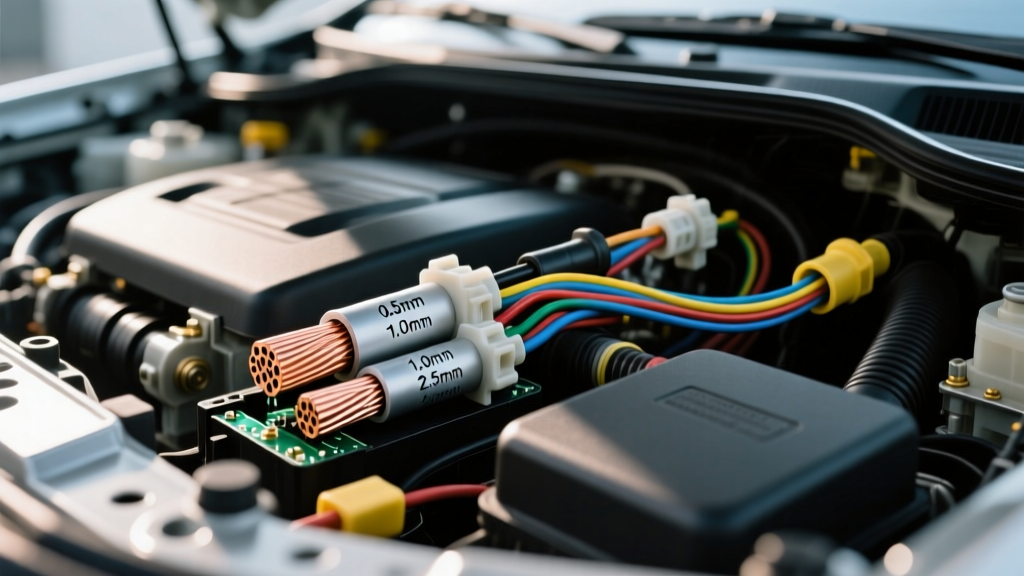
Understanding the Metric Wire Gauge Paradigm
When diagnosing electrical faults in modern European and Asian vehicles, technicians frequently encounter a fundamental mismatch in repair methodologies: the difference between American Wire Gauge (AWG) and the metric wire gauge system. While domestic vehicles traditionally rely on AWG (based on wire diameter), import manufacturers such as Volkswagen, BMW, Toyota, and Honda design their wiring harnesses using the metric system, which specifies wire size by cross-sectional area in square millimeters (mm²). This distinction is governed by international standards like ISO 6722-1 Road vehicles — Unscreened low-tension cables, which dictates strict parameters for strand count, insulation thickness, and thermal endurance.
Misidentifying a metric wire gauge and attempting a repair with a standard AWG wire or incorrect crimp die is a leading cause of intermittent voltage drops, CAN-bus communication faults, and melted connector housings. This step-by-step troubleshooting flow is designed to help automotive electrical specialists isolate, verify, and properly repair metric wire gauge circuits using OEM-compliant diagnostic decision trees.
Phase 1: Symptom Isolation & Voltage Drop Mapping
Before cutting into any harness, you must verify that the fault is indeed a wire gauge or termination issue rather than a failed component. The most common symptom of an undersized or poorly spliced metric wire is a voltage drop under load, which manifests as dimming lights, slow window regulators, or ECU brown-out resets.
Step 1.1: The Loaded Voltage Drop Test
- Setup: Connect your digital multimeter (DMM) in DC voltage mode. Place the red probe on the battery positive post and the black probe on the component's power pin (e.g., Pin 1 of the fuel pump connector).
- Load the Circuit: Activate the circuit. For a 2.5mm² ABS pump feed, the circuit must be tested under active load, not just key-on engine-off (KOEO).
- Threshold Analysis: According to SAE J1128 Low Tension Primary Cable Standards, a healthy circuit should exhibit no more than a 0.1V drop per connector and a total circuit drop of less than 0.5V. If your DMM reads a 1.2V drop across a 1.5mm² relay feed wire, you have isolated a high-resistance fault.
Step 1.2: Isolate the Fault Zone
Move the DMM probes incrementally along the circuit. If the voltage drop occurs between the intermediate connector (e.g., VW's X10 bulkhead connector) and the component, the fault lies in that specific wire segment or its terminal crimp.
Phase 2: Wire Gauge Verification & The 'Frankenstein' Splice
Once the faulty segment is isolated, the next step in the troubleshooting flow is to verify the exact metric wire gauge and inspect for previous, substandard repairs.
Step 2.1: Reading the Insulation Stamp
OEM metric wires, such as FLRY-A or FLRY-B types, have their specifications printed directly on the insulation. You will typically see markings like FLRY-B 0.75 or 0.50 mm². Do not rely on visual thickness comparisons; a 0.5mm² metric wire has an outer diameter of approximately 2.1mm, which looks nearly identical to 20 AWG but carries different current limits and requires a specific crimp profile.
Step 2.2: Identifying the AWG/Metric Mismatch
The most common failure mode in aging imports is the 'Frankenstein splice'—a previous technician's attempt to repair a broken metric wire using standard AWG wire and a generic butt connector. For example, splicing an 18 AWG wire (0.82mm²) into a 0.75mm² OEM harness seems logical on paper, but the physical stranding differences cause catastrophic crimp failures. The 18 AWG wire is slightly thicker, causing the crimp barrel to deform, while the metric wire's fine stranding (often 19 strands for 0.75mm²) gets sheared by the improper crimp tool, leading to galvanic corrosion and eventual open-circuit failures.
Phase 3: Metric to AWG Conversion & Ampacity Chart
To properly diagnose and repair the circuit, you must map the OEM metric wire gauge to its closest AWG equivalent for diagnostic substitution, while strictly using metric dies for the final repair. Use the following reference chart to verify that the installed wire gauge is sufficient for the circuit's fused amperage.
| Metric Size (mm²) | Approx. AWG Equivalent | Strand Count (Typical) | Max Ampacity (60°C) | Common Automotive Application |
|---|---|---|---|---|
| 0.35 mm² | 22 AWG | 7 | 9 Amps | CAN-Bus lines, Sensor signals, Airbag squibs |
| 0.50 mm² | 20 AWG | 19 | 11 Amps | LED lighting, Injector triggers, ECU grounds |
| 0.75 mm² | 18 AWG | 19 | 14 Amps | Relay coils, Interior lighting, Module wake-up |
| 1.50 mm² | 15 AWG | 19 | 20 Amps | Ignition coils, Power windows, Horn circuits |
| 2.50 mm² | 13 AWG | 19 | 30 Amps | Fuel pump feeds, ABS valve feeds, Seat heaters |
| 4.00 mm² | 11 AWG | 19 | 40 Amps | Main ECU power feeds, High-current cooling fans |
| 6.00 mm² | 10 AWG | 19 | 55 Amps | Alternator B+ outputs, Starter motor feeds |
Phase 4: Terminal Pin Drag & Crimp Barrel Inspection
If the wire gauge is correct and no splices are present, the voltage drop is likely occurring at the terminal-to-pin interface inside the connector housing.
Step 4.1: The Pin Drag Test
Disconnect the component and the ECU. Using a brand-new, OEM-spec terminal pin (or a dedicated pin gauge tool from TE Connectivity Automotive Standards), insert it into the female terminal cavity. You should feel a distinct, uniform mechanical drag. If the pin slides in with zero resistance, the terminal's internal tension fingers have lost their spring tension due to thermal cycling or a previous forced insertion. The terminal must be replaced.
Step 4.2: Open-Barrel vs. Closed-Barrel Crimps
Inspect the terminal crimp barrel. Volkswagen and Audi predominantly use open-barrel (stamped and formed) terminals, which require a precise 'B' or 'heart' shaped crimp profile. BMW and Mercedes-Benz often utilize closed-barrel terminals. Using a standard AWG closed-barrel crimping tool on a VW open-barrel 0.5mm² terminal will fold the brass wings improperly, creating a high-resistance point that will melt the plastic connector housing under a 15-amp load.
Phase 5: OEM-Compliant Repair Protocols
Once the exact metric wire gauge and terminal type are identified, execute the repair using the following strict protocols to ensure long-term reliability.
- Stripping: Use a wire stripper with dedicated metric gauge holes. Stripping a 0.35mm² wire with an 22 AWG hole often nicks the copper strands, reducing the cross-sectional area and creating a localized hot spot.
- Crimping: Use a ratcheting crimp tool equipped with metric-specific dies (e.g., 0.35-0.5, 0.75-1.0, 1.5-2.5). The ratchet must complete the full cycle to ensure the proper compression ratio.
- Sealing: If the repair is in an exposed area (e.g., wheel well or engine bay), use adhesive-lined polyolefin heat shrink tubing with a 3:1 shrink ratio. The internal thermoplastic adhesive must melt and flow out of the ends of the tubing, creating a watertight seal against capillary action and copper oxidation.
- Ultrasonic Welding (Alternative): For high-current metric wires (4.0mm² and above) where splicing is unavoidable, OEM dealerships increasingly utilize ultrasonic welding to fuse the copper strands at a molecular level, eliminating the mechanical resistance inherent in traditional crimp barrels.
Real-World Case Study: BMW E90 FRM Module Melted Connector
A classic example of metric wire gauge troubleshooting involves the BMW E90 Footwell Module (FRM). Vehicles frequently present with dead low-beam headlights and interior lighting faults. The root cause is often found at the X11020 connector, specifically Pin 13 (White/Red/Blue stripe), which carries the lighting feed.
In a documented case, a previous shop attempted to repair a chafed 0.75mm² wire using a standard 18 AWG butt splice and electrical tape. Because the 18 AWG wire was marginally thicker and lacked the fine stranding of the OEM FLRY-B 0.75mm² wire, the crimp was loose. Over three years of thermal cycling, the loose crimp developed micro-arcing and increased resistance. When the halogen headlights drew their full 55-watt load (approx. 4.5 amps per side), the voltage drop across the bad splice generated enough heat to melt the TE Connectivity connector housing and fuse the terminal to the FRM module pins. By following the metric wire gauge troubleshooting flow, the technician correctly identified the mismatched splice, removed the damaged X11020 housing, and installed a new OEM 0.75mm² pigtail using a proper open-barrel crimp die, restoring the circuit to factory specifications without triggering the FRM's internal short-circuit lockout.
Summary
Troubleshooting metric wire gauge circuits requires abandoning domestic AWG assumptions. By rigorously following this diagnostic flow—mapping voltage drops, verifying mm² cross-sections, avoiding AWG mismatches, and utilizing metric-specific crimping tools—you ensure that import vehicle electrical systems operate with the precise low-resistance conductivity intended by their original engineers.