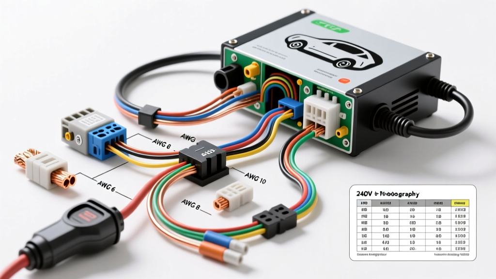
The Core Question: What Gauge Wire for 240V Automotive Applications?
When customizing heavy-duty trucks, overland expedition vehicles, or mobile command centers, integrating 240V AC power is a game-changer. Whether you are wiring a high-output pure sine wave inverter to run mobile welding equipment, or hardwiring a Level 2 Electric Vehicle Supply Equipment (EVSE) charger into a fleet garage, the question remains: what gauge wire for 240v applications is required? Unlike standard 12V DC automotive circuits where current is massive and wire gauge is dictated primarily by amperage, 240V AC systems require strict adherence to insulation ratings, continuous load derating, and mechanical vibration standards.
In the automotive and mobile power sector, 240V AC is typically split-phase (120/240V) or straight 240V single-phase. Sizing the wire incorrectly doesn't just cause voltage drop; it creates severe arc flash hazards, insulation melt-downs, and catastrophic inverter failures. Below is a complete wiring diagram walkthrough and gauge reference for 240V mobile power and EV charging integrations.
240V AC Amperage vs. AWG Sizing Chart (Copper)
The following table outlines the minimum copper wire gauge required for 240V automotive and EVSE applications. These ratings assume 75°C to 90°C rated insulation (THHN, XHHW, or MTW) and adhere to the 80% continuous load rule mandated by the NFPA 70 National Electrical Code (NEC) Article 210.20.
| Max Continuous Amperage | AWG Size (Copper) | Typical Auto/Overland Application | Standard NEMA Receptacle Match |
|---|---|---|---|
| 24 Amps | 10 AWG | 3000W 240V Inverter (Surge rated) | NEMA 6-30R / L6-30R |
| 32 Amps | 8 AWG | 40A EVSE Level 2 Charger | Hardwire / NEMA 14-50 |
| 40 Amps | 6 AWG | 50A Mobile Welder / EVSE Rig | NEMA 14-50R / 6-50R |
| 48 Amps | 4 AWG | 60A+ High-Output Fleet EVSE | Direct Hardwire to Subpanel |
Complete Wiring Diagram Walkthrough: 4000W Split-Phase Inverter System
Let's walk through a real-world installation of a 4000W split-phase (120/240V) inverter system in an overland Ford F-550 expedition rig. This system powers a 240V mobile air compressor, a microwave, and a 120V auxiliary subpanel.
Step 1: The DC Input Side (Battery to Inverter)
Before addressing the 240V AC output, we must acknowledge the massive DC current required to generate that AC power. A 4000W inverter running on a 24V DC battery bank will draw approximately 185 Amps continuously, with surge spikes exceeding 300 Amps.
- Wire Gauge: 2/0 AWG (00 AWG) flexible copper welding cable.
- Insulation: EPDM or Neoprene, rated for high heat and fluid resistance.
- Termination: Tinned copper lugs, crimped using a 12-ton hydraulic hex crimper. Do not use hammer crimpers for 2/0 AWG; the compression will be inconsistent, leading to high-resistance hot spots.
- Overcurrent Protection: 250A Class T fuse mounted within 7 inches of the battery positive terminal.
Step 2: The 240V AC Output Side (Inverter to Subpanel)
Now we answer the primary question: what gauge wire for the 240V AC output? The 4000W inverter outputs 16.6 Amps at 240V. However, to accommodate continuous loads and future expansion, we wire the main trunk line to the subpanel for a 30 Amp capacity.
- Wire Gauge: 10 AWG Copper.
- Insulation Type: MTW (Machine Tool Wire) or THHN. MTW is highly recommended in automotive environments due to its superior flexibility and resistance to high-frequency vibration compared to standard THHN.
- Conductor Colors: Black (Hot 1 / L1), Red (Hot 2 / L2), White (Neutral), Green (Equipment Ground).
- Routing: All AC wiring must be routed in flexible non-metallic conduit (liquid-tight) to prevent chafing against the vehicle chassis. Maintain a minimum 12-inch separation from sensitive 12V DC CAN-bus data lines to prevent electromagnetic interference (EMI).
Step 3: NEMA L14-30R Receptacle Pinout
For exterior 240V hookups, we terminate the 10 AWG cable into a twist-lock NEMA L14-30R receptacle. The pinout configuration is critical:
- Pin X (Brass Screw): Black Wire (L1 - 120V to Neutral)
- Pin Y (Brass Screw): Red Wire (L2 - 120V to Neutral, 240V across X and Y)
- Pin W (Silver Screw): White Wire (Neutral)
- Pin G (Green Screw): Green Wire (Ground)
Expert Tip: Torque the terminal screws on the L14-30R to exactly 14 in-lbs. Under-torquing causes arcing under heavy inductive loads (like starting an air compressor), while over-torquing can strip the brass threads and compromise the mechanical grip.
EVSE Level 2 Hardwire Integration (240V AC)
When installing a permanent Level 2 EV charger (EVSE) in an automotive shop or a residential garage for fleet vehicles, the wiring requirements shift slightly. The SAE J2293 EVSE Standard and NEC Article 625 dictate strict safety protocols for vehicle charging infrastructure.
For a standard 48-Amp continuous EVSE, the breaker must be sized at 125% of the continuous load, requiring a 60 Amp breaker. Therefore, the wire gauge must be sized for 60 Amps.
Wire Sizing and Derating for EVSE
- Target Amperage: 60A Breaker / 48A Continuous.
- Required Wire Gauge: 4 AWG Copper THHN/THWN-2.
- Conduit Fill: When pulling four current-carrying conductors (or three plus a ground) through rigid metal or PVC conduit, ensure you do not exceed 40% conduit fill capacity. Overcrowding prevents heat dissipation, requiring you to apply NEC Table 310.15(C)(1) ampacity derating factors.
- Grounding: An insulated 8 AWG green grounding conductor must be pulled with the circuit. The vehicle relies on a pristine ground reference to complete the EVSE handshake protocol via the proximity and control pilot pins on the J1772 connector.
Insulation Specifications: MTW vs. THHN vs. XLPE
When sourcing wire for 240V automotive applications, the jacket material is just as important as the copper cross-section. Standard automotive primary wire (SAE J1128 GPT) is only rated for 60V DC and must never be used for 240V AC mains wiring, even if the copper gauge is correct.
- MTW (Machine Tool Wire):
- The gold standard for mobile 240V setups. MTW features a flexible, oil-resistant, and moisture-resistant PVC jacket. It handles the constant micro-vibrations of a diesel truck chassis without the insulation cracking or work-hardening the copper strands.
- THHN (Thermoplastic High Heat-resistant Nylon-coated):
- Excellent for stationary EVSE conduit runs. It is highly resistant to heat and chemicals but is relatively stiff. In mobile applications, THHN can suffer from insulation fatigue where the wire flexes near the termination lugs.
- XLPE (Cross-Linked Polyethylene):
- Used in high-temperature zones near exhaust manifolds or turbochargers. XLPE can withstand continuous temperatures up to 125°C (compared to 90°C for THHN) and offers superior dielectric strength.
Real-World Troubleshooting & Voltage Drop Analysis
Even if you select the correct gauge wire for 240V, poor termination practices will ruin the system. The most common failure mode in high-current 240V mobile systems is thermal runaway at the lug connections.
The Voltage Drop Formula
According to the Victron Energy Wiring Unlimited Guide, voltage drop on the AC side should not exceed 3% for branch circuits. The formula for single-phase 240V AC voltage drop is:
VD = (2 x K x I x L) / CM
- K = Specific resistance of copper (12.9 ohms per mil-foot at 75°C)
- I = Current in Amps
- L = One-way length of the wire in feet
- CM = Circular mils of the wire gauge (e.g., 10 AWG = 10,380 CM)
If you are running 30 Amps of 240V power from an inverter to a rear-mounted AC compressor on a 170-inch wheelbase Sprinter van (approx. 25 feet of wire), using 10 AWG wire yields a voltage drop of roughly 1.8V (less than 1%). This is well within safe operational parameters. However, if you step up to a 50A welder circuit over the same distance, 10 AWG would result in a dangerous 15% voltage drop, requiring an upgrade to 4 AWG.
Thermal Imaging and Torque Verification
After completing any 240V automotive wiring, perform a thermal sweep. Run the system at 80% capacity for 30 minutes. Use an infrared thermography camera to scan all breaker terminals, busbars, and NEMA receptacles. Any connection showing a temperature delta greater than 15°F above ambient room temperature indicates a high-resistance joint. Power down, disconnect, clean the copper with a wire brush, apply a light coat of electrical contact cleaner, and re-torque to the manufacturer's specification using a calibrated torque screwdriver.
Summary Checklist for 240V Auto Wiring
- Calculate Continuous Load: Multiply the continuous amperage by 1.25 to determine breaker and wire sizing.
- Select Proper Insulation: Use MTW for mobile/vibration environments; use THHN for stationary conduit EVSE runs.
- Maintain Separation: Keep 240V AC lines physically separated from 12V DC CAN-bus and audio wiring.
- Torque to Spec: Never guess terminal torque. Use a calibrated inch-pound torque driver.
- Verify Grounding: Ensure the equipment grounding conductor is continuous and bonded correctly to the vehicle chassis or main grounding busbar.