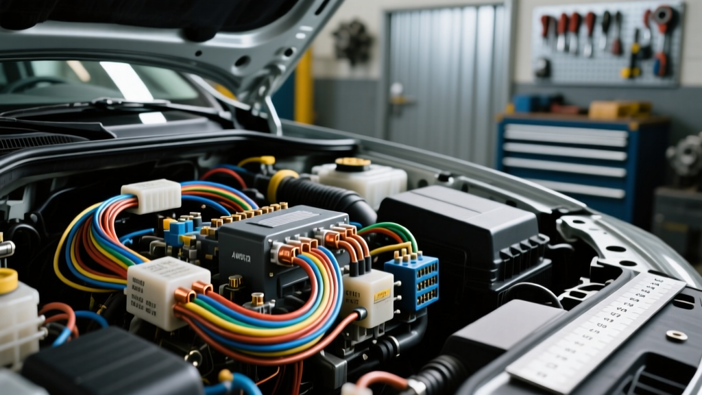
Automotive AWG Wire Gauge Explained: The Physics of 12V Systems
When building, modifying, or repairing vehicle electrical systems, understanding how wire gauge explained through the lens of automotive physics is critical. Unlike household alternating current (AC) systems that operate at 120V or 240V, automotive direct current (DC) systems operate at a nominal 12V (actually 13.8V to 14.4V when the alternator is charging). Because power (Watts) equals Voltage multiplied by Current (Amps), a low-voltage system requires significantly higher amperage to deliver the same wattage. This high current makes resistance the ultimate enemy of automotive wiring.
The American Wire Gauge (AWG) system is a logarithmic stepped system used to specify the diameter of electrically conducting wire. In the AWG system, the larger the gauge number, the smaller the physical wire diameter. For example, a 10 AWG wire is substantially thicker and has less electrical resistance than a 16 AWG wire. In automotive applications, selecting the correct gauge is not just about preventing melted insulation; it is about ensuring sensitive electronic control units (ECUs), fuel pumps, and ignition systems receive the precise voltage required to operate efficiently.
Comprehensive AWG Specification & Ampacity Chart
The following reference table details standard copper wire specifications commonly used in automotive chassis and engine bay wiring. Ampacity ratings are based on standard SAE J1128 Low Tension Primary Cable guidelines for single conductors in free air.
| AWG Size | Strand Count | Nominal O.D. (inches) | Copper Area (Circular Mils) | Resistance (Ω/1000ft @ 20°C) | Max Amps (Chassis) | Max Amps (Engine Bay) |
|---|---|---|---|---|---|---|
| 18 AWG | 16 | 0.050 | 1,624 | 6.385 | 10A | 6A |
| 16 AWG | 26 | 0.063 | 2,583 | 4.016 | 15A | 10A |
| 14 AWG | 41 | 0.079 | 4,110 | 2.525 | 20A | 15A |
| 12 AWG | 65 | 0.099 | 6,530 | 1.588 | 30A | 20A |
| 10 AWG | 105 | 0.125 | 10,380 | 0.998 | 45A | 30A |
| 8 AWG | 168 | 0.158 | 16,510 | 0.628 | 70A | 50A |
| 4 AWG | 266 | 0.250 | 41,740 | 0.248 | 150A | 120A |
Understanding the Derating Factor in Engine Compartments
A common mistake in automotive wiring is ignoring ambient temperature. The 'Max Amps (Chassis)' column assumes an ambient temperature of roughly 86°F (30°C). However, under-hood temperatures routinely exceed 220°F (104°C) near exhaust manifolds. As copper heats up, its electrical resistance increases, which generates more heat—a dangerous feedback loop known as thermal runaway. When routing wire through the engine bay, you must derate the ampacity by at least 30% to 40%, or utilize high-temperature insulation types like Cross-Linked Polyethylene (XLPE), commonly designated as GXL or TXL wire, which can withstand continuous temperatures up to 125°C or 150°C.
Voltage Drop: The True Metric for Automotive Sizing
While ampacity charts prevent fires, they do not guarantee proper component operation. Voltage drop is the actual loss of electrical potential as current travels through the resistance of the wire. In a 12V system, a drop of just 1.2V (10%) can cause a fuel pump to lose 20% of its flow rate or cause an ECU to reset under load.
The formula for calculating voltage drop in a DC circuit is:
VD = (2 × L × I × R) / 1000
- VD = Voltage Drop
- L = One-way length of the wire in feet
- I = Current draw in Amps
- R = Resistance of the wire per 1,000 feet (from the chart above)
Real-World Example: Consider an aftermarket Walbro 255lph fuel pump drawing 12 Amps, located 15 feet from the battery (30 feet total circuit length including the ground return). If you use 14 AWG wire (R = 2.525), the voltage drop is 4.5V, leaving only 9.5V at the pump—completely unacceptable. Upgrading to 10 AWG wire (R = 0.998) reduces the drop to 1.79V, delivering a healthy 12.6V to the pump.
Real-World Automotive Circuit Applications
Applying these specifications requires understanding specific automotive circuits, standard wire color codes, and connector ecosystems.
High-Current Starter and Alternator Circuits
Starters can draw 150A to 300A+ during cranking. Alternators on modern vehicles frequently output 140A to 200A. These circuits require 4 AWG to 1/0 AWG fine-strand welding cable to maintain flexibility and minimize voltage drop. Connections should utilize heavy-duty copper ring terminals, crimped with a hydraulic or heavy hex-crimp tool, and secured to 3/8-inch or 5/16-inch studs with a star washer to bite through corrosion. Standard wire color coding dictates heavy Red for battery positive and heavy Black for chassis ground.
EFI Fuel Pump and Injector Harnesses
Electronic Fuel Injection (EFI) systems demand clean, stable voltage. The main fuel pump feed should be wired using 12 AWG or 10 AWG wire (typically Grey with a Black tracer in GM applications, or Dark Green in Ford). Injectors, which draw between 1A and 4A each, are typically wired using 18 AWG or 16 AWG wire. For these connections, the Delphi Metri-Pack 2.8 series connectors are the industry standard, providing excellent vibration resistance and moisture sealing. Always use the correct extraction tool and ensure the terminal tang clicks securely into the plastic housing.
Lighting and Accessory Relays
When wiring off-road lights, cooling fans, or winches, ISO mini relays (Bosch style) are standard. The control circuit (pins 85 and 86) draws less than 0.5A and can be wired with 18 AWG wire. The load circuit (pins 30 and 87) must be sized for the accessory. A standard 30A relay powering a 150W light bar (approx. 11A draw) requires 14 AWG wire for runs under 10 feet, terminating in Weather-Pack or Deutsch DT connectors to ensure waterproof integrity in harsh environments.
Troubleshooting Undersized Wiring and Thermal Runaway
Diagnosing voltage issues requires moving beyond simple continuity tests. A wire with a single frayed strand inside the insulation will pass a multimeter continuity test but will fail catastrophically under load. To properly diagnose wire gauge and connection issues, perform a millivolt drop test while the circuit is actively loaded.
- Set your digital multimeter to the DC millivolt (mV) scale.
- Connect the positive probe to the battery positive terminal and the negative probe to the component's positive input pin.
- Activate the circuit (e.g., turn on the cooling fan or crank the engine).
- A reading above 200mV (0.2V) on the positive side, or 100mV (0.1V) on the ground side, indicates excessive resistance. This points to either an undersized wire gauge, a corroded bulkhead connector, or a failing crimp terminal.
Furthermore, inspect relay sockets for melted plastic. A melted ISO relay socket is almost always a symptom of voltage drop generating heat at the terminal interface, often exacerbated by using cheap, stamped-brass terminals instead of high-quality copper-alloy terminals. Upgrading the wiring harness to a properly sized AWG and utilizing sealed, gold-plated terminals will resolve the thermal issue and restore optimal system voltage.