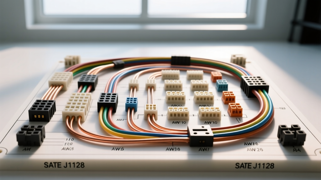
The Physics of Copper in 12V and 48V Automotive Architectures
When engineering, modifying, or diagnosing automotive electrical systems, the margin for error is significantly smaller than in residential AC wiring. Unlike a 120V or 240V home circuit where high voltage pushes current through long runs with minimal loss, a 12V DC automotive system requires massive amperage to deliver equivalent wattage. Consequently, consulting an accurate american wire gauge resistance table copper ohms per 1000 ft is the foundational step in preventing voltage drop, component starvation, and catastrophic thermal events. In modern vehicles featuring 48V mild-hybrid systems and high-amperage EV charging architectures, understanding the exact resistivity of copper under dynamic thermal loads is not just academic—it is a critical safety requirement.
Master American Wire Gauge Resistance Table: Copper Ohms Per 1000 Ft
The following reference table outlines the DC resistance of bare, annealed copper wire. However, automotive environments rarely operate at room temperature. Therefore, this table includes calculated resistance values at 105°C (221°F), which represents a standard under-hood ambient temperature threshold for SAE J1128 GXL (cross-linked polyethylene) primary wire. Ampacity ratings reflect chassis wiring conditions (single conductor in free air), not bundled harness conditions.
| AWG Size | SAE Stranding | Nominal OD (in) | Ohms/1000 ft @ 20°C | Ohms/1000 ft @ 105°C | Max Ampacity (Chassis) |
|---|---|---|---|---|---|
| 18 AWG | 16/30 | 0.040 | 6.385 Ω | 8.51 Ω | 16 A |
| 16 AWG | 26/30 | 0.051 | 4.016 Ω | 5.35 Ω | 22 A |
| 14 AWG | 41/30 | 0.064 | 2.525 Ω | 3.36 Ω | 32 A |
| 12 AWG | 65/30 | 0.081 | 1.588 Ω | 2.12 Ω | 41 A |
| 10 AWG | 105/30 | 0.102 | 0.9989 Ω | 1.33 Ω | 55 A |
| 8 AWG | 168/30 | 0.128 | 0.6282 Ω | 0.84 Ω | 73 A |
| 4 AWG | 266/27 | 0.204 | 0.2485 Ω | 0.33 Ω | 125 A |
| 1/0 AWG | 426/27 | 0.325 | 0.0983 Ω | 0.13 Ω | 200 A |
Temperature Derating: Why 20°C Data Fails Under the Hood
A common mistake among novice automotive electricians is sizing wire based solely on standard 20°C (68°F) resistance tables. Copper possesses a positive temperature coefficient of resistance. As the ambient temperature under the hood increases—especially near exhaust manifolds, turbochargers, or high-load alternators—the physical resistance of the copper increases proportionally. According to data published by the Copper Development Association, the temperature coefficient (α) for annealed copper is approximately 0.00393 per degree Celsius.
Calculating Hot Resistance in Real-Time
To determine the actual resistance of a wire run in a hot engine bay, you must apply the thermal correction formula:
R_hot = R_cold × [1 + α × (T_hot - T_cold)]
For example, if you are routing a 12 AWG battery feed to an auxiliary fuse block, the base resistance is 1.588 Ω per 1000 ft at 20°C. If the wire is routed near the cylinder head where ambient temperatures stabilize at 105°C, the resistance jumps to 2.12 Ω per 1000 ft—a 33% increase. If your circuit draws 30 amps over a 10-foot run (20 feet total out-and-back), your voltage drop increases from 0.95V to 1.27V. In a 12V system where the alternator is outputting 14.2V, delivering less than 13V to sensitive ECU relays can cause erratic shifting, misfires, or CAN bus communication faults.
Real-World Diagnostic Scenarios: Beyond the Continuity Tester
Never rely on a standard multimeter continuity test to diagnose automotive wiring faults. A single, frayed strand of 24 AWG copper can pass a continuity test (completing the circuit for the multimeter's low-current LED), but will instantly bottleneck under a 15-amp load. Professional diagnostics require dynamic voltage drop testing under load.
Scenario A: Starter Solenoid Feed Circuit (1/0 AWG GXL)
The starter motor circuit represents the highest amperage draw in a standard internal combustion vehicle, frequently exceeding 400 amps during initial inrush. The factory wiring typically utilizes 1/0 AWG GXL wire with heavy-duty ring terminals crimped onto the battery positive post and the starter solenoid stud.
- Symptom: Engine cranks slowly; dashboard lights dim significantly during cranking.
- Diagnostic Step: Set the multimeter to DC Volts. Place the red probe on the battery positive post and the black probe directly on the starter solenoid copper stud (not the nut). Have an assistant crank the engine.
- Specification: Per SAE J1128 and OEM diagnostic standards, the maximum allowable voltage drop on the positive supply side under full cranking load is 0.5V. If you read 1.2V, the issue is not a bad starter; it is high resistance in the cable or the crimp joint.
- Failure Mode: Galvanic corrosion between the copper lug and the aluminum/steel terminal post, or a poorly executed mechanical crimp that failed to compress the wire strands, creating microscopic air gaps that increase resistance and generate localized heat.
Scenario B: High-Speed CAN Bus Diagnostics (20 AWG / 24 AWG)
Modern powertrain control modules (PCMs) communicate via High-Speed Controller Area Network (CAN) buses. These networks typically utilize 20 AWG or 24 AWG unshielded twisted pair (UTP) copper wiring. Because CAN bus operates on differential voltage signaling (typically 2.5V to 3.5V), precise wire resistance and termination are mandatory.
- Pin Configuration: On a standard OBD-II J1962 diagnostic connector, Pin 6 is CAN-High (often white or yellow) and Pin 14 is CAN-Low (often green or blue).
- Termination Resistance: The network requires exactly 60 ohms of total resistance to prevent signal reflection. This is achieved via two 120-ohm terminating resistors located at the physical ends of the bus (usually inside the PCM and the instrument cluster).
- Diagnostic Step: With the battery disconnected, measure resistance between Pin 6 and Pin 14. A reading of 120 ohms indicates an open circuit in one of the terminating modules or a severed wire. A reading of 30 ohms indicates an extra, unauthorized terminating resistor has been added to the network, dragging down the differential voltage and causing U-codes (network communication DTCs).
Stranding, Work Hardening, and SAE Compliance
Automotive copper wire must be highly flexible to withstand chassis vibration, engine movement, and thermal expansion cycles. Solid core wire, while possessing marginally lower resistance per 1000 ft due to the absence of air gaps between strands, is strictly prohibited in mobile applications. Solid copper undergoes work hardening and will fracture under harmonic vibration.
SAE J1128 compliant GXL and TXL wires utilize specific fine-stranding configurations (e.g., 105 strands of 30 AWG wire to make a 10 AWG cable). When terminating these fine-strand wires, it is imperative to use ratcheting crimpers designed for the specific AWG and insulation type (e.g., Weather-Pack or Deutsch DT series). Soldering fine-strand automotive wire is generally discouraged by OEMs like Bosch Automotive Electrics because solder wicks into the wire strands via capillary action, creating a rigid, brittle point just outside the connector pin that is highly susceptible to vibration-induced fatigue and subsequent high-resistance failure.
Summary of Best Practices
Always calculate voltage drop using the 105°C resistance values when routing wires through the engine bay. Ensure your crimp joints are mechanically sound, utilizing adhesive-lined heat shrink to block moisture ingress and prevent copper oxidation. By treating the american wire gauge resistance table as a dynamic, temperature-dependent tool rather than a static chart, you ensure the longevity and reliability of complex automotive electrical systems.