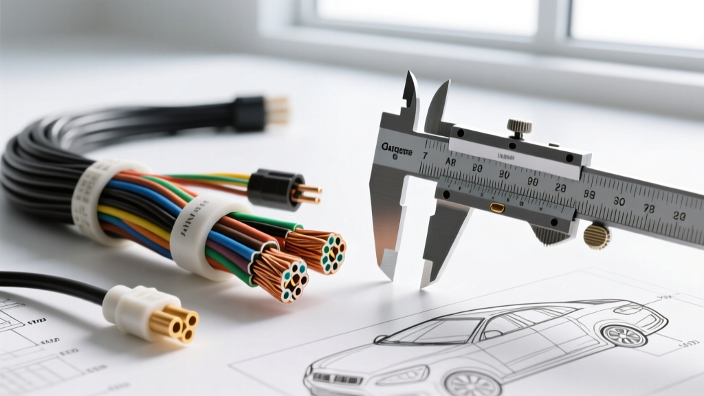
The Challenge of Unmarked Automotive Wiring
When performing a harness repair, fabricating a custom relay kit, or diagnosing a voltage drop, knowing how to tell gauge of wire accurately is the difference between a reliable circuit and a melted firewall. Unlike residential NM-B (Romex) cable, automotive primary wire rarely features printed jacket markings. Over time, engine bay heat, oil exposure, and abrasion strip away any factory printing, leaving technicians with unmarked copper strands. Guessing the American Wire Gauge (AWG) or metric cross-sectional area by eye leads to catastrophic voltage drop, ECU communication failures, and thermal events.
This technical reference provides exact methodologies for identifying unmarked automotive wire using digital calipers, strand-count mathematics, and insulation standard cross-references. We will also cover the critical differences between North American SAE standards and European ISO/DIN metric sizing.
Method 1: Digital Caliper Measurement (Conductor vs. OD)
The most common mistake novice technicians make is measuring the Outer Diameter (OD) of the wire including the insulation. In automotive applications, this is a guaranteed path to misidentification due to the SAE J1128 Standard, which defines three distinct insulation wall thicknesses for low-tension primary cable:
- TXL (Thin Wall): Cross-linked polyethylene, designed for tight harness looms.
- GXL (General Wall): Standard OEM thickness for most under-hood applications.
- SXL (Special/Thick Wall): Heavy-duty insulation for high-heat zones and battery cables.
For example, the OD of a 14 AWG SXL wire (approx. 2.67mm) is nearly identical to the bare conductor diameter of an 8 AWG wire (2.59mm). If you measure the OD, you might mistakenly use an 8 AWG crimp barrel, resulting in a loose connection that will arc and fail. You must always strip the insulation and measure the bare copper conductor bundle.
Bare Conductor Diameter to AWG Chart
| AWG Size | Conductor Diameter (mm) | Conductor Diameter (in) | Typical Automotive Application |
|---|---|---|---|
| 18 AWG | 1.02 mm | 0.0403 in | ECM Sensors, Injectors, 5V Reference |
| 16 AWG | 1.29 mm | 0.0508 in | Lighting Circuits, Horn Relays, CAN Bus |
| 14 AWG | 1.63 mm | 0.0641 in | Fuel Pumps, Power Windows, 15A Fused |
| 12 AWG | 2.05 mm | 0.0808 in | High-Amp Lighting, Amplifier Power, 20A Fused |
| 10 AWG | 2.59 mm | 0.1019 in | Alternator B+ Output, Starter Solenoid Feed |
| 8 AWG | 3.26 mm | 0.1285 in | Main Battery Relocation, High-Wattage Audio |
Method 2: The Strand Count & Single Strand Measurement Formula
Automotive wire is highly flexible stranded copper. If the wire is heavily oxidized, crushed, or splayed at the terminal, a caliper measurement of the bundle will be inaccurate. Instead, measure a single strand and use the Circular Mil (CM) or square millimeter (mm²) formula to determine the true gauge.
Step-by-Step Strand Calculation
- Isolate a single copper strand from the bundle.
- Use a precision micrometer or digital caliper to measure the strand diameter (e.g., 0.25mm).
- Calculate the cross-sectional area of that single strand:
Area = π × (radius)². (e.g., π × 0.125² = 0.049 mm²). - Count the total number of strands in the wire bundle (e.g., 26 strands).
- Multiply the single strand area by the total strand count:
0.049 mm² × 26 = 1.27 mm². - Cross-reference the result with standard AWG tables. A 1.27 mm² to 1.31 mm² total area confirms 16 AWG.
This mathematical approach is the gold standard for forensic electrical diagnostics when dealing with damaged or frayed harness ends where the wire geometry has been compromised.
Method 3: Metric (mm²) to AWG Conversion for Import Vehicles
If you are working on European or Asian vehicles (BMW, Volkswagen, Volvo, Toyota), the harness is likely manufactured to ISO 6722 or DIN 72551 standards. These vehicles do not use AWG; they use metric cross-sectional area (mm²). Attempting to force AWG terminals onto metric wire often results in improper crimp compression.
Metric to AWG Cross-Reference Table
| Metric Size (mm²) | Approximate AWG Equivalent | Typical Import Vehicle Application |
|---|---|---|
| 0.35 mm² | 22 AWG | CAN-Bus High/Low, Airbag Clockspring |
| 0.50 mm² | 20 AWG | O2 Sensor Heaters, MAP Sensors |
| 0.75 mm² | 18 AWG | ABS Wheel Speed Sensors, Solenoids |
| 1.00 mm² | 16 AWG | Interior Lighting, Switchgear Illumination |
| 1.50 mm² | 14 AWG | Fuel Injectors, Ignition Coils (COP) |
| 2.50 mm² | 12 AWG | Starter Motor Control, High-Current Modules |
| 4.00 mm² | 10 AWG | Alternator Main Output, Glow Plug Busses |
Real-World Automotive Wire Colors & Gauge Pairings
While wire color never officially dictates gauge, OEM harness manufacturers follow strict color-coding conventions for specific circuits. Recognizing these patterns can help you verify your caliper measurements against expected circuit loads.
- GM LS-Series Alternators: The main B+ output stud utilizes a heavy ring terminal on 10 AWG Red wire. However, the 4-pin regulator pigtail directly adjacent to it uses 18 AWG (typically Grey, Red/White, and Brown). Confusing these during a custom bracket fabrication will result in immediate PCM voltage regulation failure.
- Ford 5.0L Coyote Injectors: The fuel injector pigtails utilize 20 AWG wire to minimize harness bulk inside the corrugated nylon loom. These wires carry high-frequency PWM signals from the PCM. Using 16 AWG wire here makes the harness too stiff, leading to stress fractures at the connector backshell.
- Toyota 2JZ-GTE VVT-i: The VVT solenoid connector typically features 18 AWG wire with a Black/White tracer for the 12V ignition feed, and a solid color for the ECU ground trigger.
Failure Modes: When Wire Gauge Deceives You
Even with proper measurement techniques, modern aftermarket wiring introduces variables that can deceive technicians. Be aware of the following failure modes when identifying and selecting replacement wire:
1. Copper Clad Aluminum (CCA) vs. Oxygen-Free Copper (OFC)
Cheap aftermarket wire sold on online marketplaces is often CCA. CCA wire has the exact same outer diameter and bare conductor diameter as pure copper, meaning your calipers will read it as the correct AWG. However, aluminum has roughly 60% higher electrical resistance than copper. A 10 AWG CCA wire will suffer the same voltage drop as an 8 AWG pure copper wire, leading to dim headlights and weak starter cranking. The Test: Take a razor blade and scrape the surface of a bare strand. If the core is silver/white, it is CCA. If it is copper all the way through, it is safe for high-amp automotive use.
2. Oversized Insulation (The 'Look' Trap)
Many low-quality 12 AWG wires are manufactured with ultra-thick, cheap PVC insulation to make the wire look like 8 AWG or 6 AWG on the retail spool. Always rely on the stripped conductor measurement. Furthermore, thick PVC insulation prevents the wire from fitting into standard automotive weather-seals. For example, a Delphi Weather-Pack connector requires specific silicone seals based on the wire OD. If you use a wire with artificially thick insulation, the 12-10 AWG red seal will not slide over the jacket, forcing you to use an oversized seal that will allow water ingress and subsequent terminal corrosion.
3. High-Temperature Tefzel (PTFE) Wire
In motorsports and aerospace applications, Tefzel-insulated wire (MIL-DTL-22759/16) is common. Tefzel has incredibly thin, dense insulation. A 14 AWG Tefzel wire has an OD of only 1.9mm. Technicians used to standard PVC SAE wire will look at this 14 AWG wire and assume it is 18 AWG or 20 AWG due to its slim profile. Always trust the caliper on the bare copper, never the visual profile of the jacket.
Authoritative References
- SAE International J1128 Standard - Low Tension Primary Cable specifications and insulation wall thickness definitions.
- The Engineering Toolbox AWG Data - Mathematical formulas for Circular Mils, metric conversions, and resistance per foot calculations.
- Madsen Wire & Cable Sizing Guide - Industry-standard ampacity charts and stranded wire diameter tolerances.