The Short Answer: How Many Amps for 14 Gauge Wire?
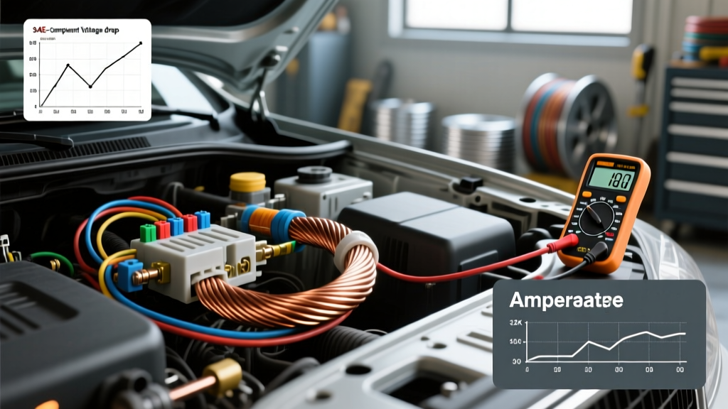
When planning an automotive electrical upgrade, one of the most common questions we encounter on the bench is: how many amps for 14 gauge wire can you safely push? The short answer is that 14 AWG stranded copper wire is rated for 15 amps continuous in a bundled chassis harness according to SAE J1128 standards. In free air, it can technically handle up to 20 to 25 amps before the insulation begins to degrade. However, in a 12V to 14.4V automotive system, thermal melting is rarely your primary concern. The true limiting factor is voltage drop.
Pushing 15 amps through 15 feet of 14 AWG wire will result in a voltage drop that can starve sensitive electronics, cause relays to chatter, or dim auxiliary lighting. To properly size your wire for modification projects, you must understand the difference between thermal ampacity and functional voltage capacity.
SAE J1128 vs. NEC: Why Automotive Wiring is Different
Many DIYers mistakenly reference the National Electrical Code (NEC) Article 240 when sizing automotive wire. Household wiring utilizes solid copper, operates at 120V/240V, and is rated in free air or specific conduit fills. Automotive wiring is governed by the SAE J1128 standard for Low Tension Primary Cable. SAE standards account for stranded copper (which has slightly higher resistance than solid core), high ambient engine bay temperatures (up to 125°C or more), and the tight bundling of harnesses which traps heat.
Because automotive systems operate at a nominal 12.6V (resting) to 14.4V (alternator charging), a 3% voltage drop limit means you can only afford to lose roughly 0.38V to 0.43V across your entire circuit. If you exceed this, your modification will underperform.
14 AWG Voltage Drop & Ampacity Chart (12V/14.4V Systems)
The chart below illustrates the maximum recommended amperage for 14 AWG GXL (General Cross-Linked) wire based on the total circuit length (power + ground). These figures maintain a strict under 3% voltage drop at an alternator charging voltage of 13.8V.
| Total Circuit Length (ft) | Max Amps (<3% Drop) | Resistance (Ohms/kft) | Recommended Mod Application |
|---|---|---|---|
| 5 Feet | 20.0 A | 2.525 | Short relay triggers, solenoid controls |
| 10 Feet | 14.5 A | 2.525 | Dual horn upgrades, auxiliary fuel pumps |
| 15 Feet | 10.0 A | 2.525 | Transmission cooler fans, interior LED arrays |
| 20 Feet | 7.5 A | 2.525 | Winch in-cabin solenoid triggers, gauge lighting |
| 25+ Feet | 6.0 A | 2.525 | Low-draw sensor feeds, ECU trigger signals |
Note: Resistance increases as copper temperature rises. If routing 14 AWG near exhaust headers or turbochargers, you must derate the ampacity by at least 20%.
Mod Project: Upgrading to High-Output Dual Horns
To put these specifications into practice, let us look at a common modification: upgrading a stock single disc horn to a high-output dual snail horn kit (e.g., Hella Supertones or Fiamm Freeway Blasters). Stock horn circuits typically use 18 AWG wire and a 10A fuse, designed for a single horn drawing 4 to 5 amps. A dual snail horn setup can draw 12 to 14 amps combined. Running this load through the factory 18 AWG wiring will cause severe voltage drop, resulting in a weak, pathetic sound and potentially melting the factory clock-spring or steering wheel switch.
Why 14 AWG is the Sweet Spot for This Mod
The horns are usually mounted in the front grille or behind the bumper, requiring roughly 8 to 10 feet of wire from the relay in the engine bay. According to our chart, 14 AWG can safely carry 14.5 amps over 10 feet while maintaining less than a 3% voltage drop. It is thick enough to handle the mechanical vibration of the engine bay and front clip, yet flexible enough to route through tight firewall grommets and factory wire looms.
Step-by-Step Relay Wiring Guide
To execute this mod, you will use a standard Bosch-style ISO mini relay (5-pin or 4-pin). We will use a 4-pin SPST (Single Pole, Single Throw) relay for simplicity.
- Pin 30 (Power In): Run 12 AWG wire from the positive battery terminal to Pin 30. Install a 20A inline ATC fuse within 8 inches of the battery post. Use an M8 ring terminal torqued to 8-10 Nm on the battery post.
- Pin 87 (Power Out to Load): Crimp a 14 AWG wire to Pin 87. Route this to the front grille. At the grille, split the 14 AWG wire into two pigtails using an adhesive-lined parallel splice, terminating in 0.250-inch (6.3mm) female spade connectors to plug into the two horns.
- Pin 86 (Switched Trigger): Tap into the factory horn trigger wire using a 14 AWG wire. Use a Posi-Tap or a proper soldered-and-heat-shrunk T-tap. Do not use cheap scotch-locks, which fray strands and invite corrosion.
- Pin 85 (Ground): Run 14 AWG from Pin 85 to a clean, unpainted chassis ground in the engine bay. Use a star washer to bite through the paint and secure with a stainless steel bolt.
Insulation Matters: GXL vs. TXL vs. SXL
When sourcing 14 AWG wire for your project, never use cheap PVC wire from a big-box hardware store. PVC insulation becomes brittle in freezing temperatures and melts easily against hot engine components. Always use cross-linked polyethylene (XLPE) automotive wire. Resources like the Painless Performance Wiring guides heavily emphasize using the correct jacket for the environment.
- GXL (General Cross-Linked): The industry standard for aftermarket chassis wiring. Rated for 125°C. Features a thinner wall than PVC, making it easier to pull through factory grommets while offering superior heat resistance.
- TXL (Thin Cross-Linked): Ultra-thin jacket. Ideal for tight spaces, such as routing through the steering column or inside door panels where space is at an absolute premium.
- SXL (Special Cross-Linked): Features a thicker jacket for high abrasion resistance. Use SXL when routing 14 AWG wire along the frame rails of an off-road vehicle where rocks and debris will strike the harness.
Real-World Failure Modes & Troubleshooting
Even if you correctly calculate how many amps for 14 gauge wire your circuit requires, poor termination practices will ruin the build. As experts at Aptiv Connection Systems note, the majority of automotive electrical failures occur at the termination point, not in the middle of the wire.
Symptom: Relay Chatter or Weak Horn Output
The Cause: Voltage drop at the 6.3mm spade connectors. If you use a cheap, non-ratcheting crimper, the copper strands are not properly compressed into the barrel of the terminal. This creates a high-resistance joint. As current flows, the joint heats up, resistance increases further, and voltage at the horn drops below the 11V threshold required for full acoustic output.
The Fix: Cut back to fresh, unoxidized copper. Use a dedicated ratcheting crimper designed for non-insulated terminals (such as an IWISS or Knoweasy tool). Apply a small dab of dielectric grease or Ox-Gard inside the female spade terminal before mating it to the horn blade to prevent moisture intrusion and copper oxide buildup.
Symptom: Green Corrosion Wicking Under the Insulation
The Cause: Using standard, single-wall heat shrink or electrical tape. Moisture enters the back of the crimp barrel and wicks up into the 14 AWG stranded wire via capillary action, creating copper oxide (the green crust) which acts as an insulator and chokes amperage.
The Fix: Always use dual-wall, adhesive-lined heat shrink (e.g., 3M EPS300). When heated, the inner thermoplastic adhesive melts and seals the wire strands completely, blocking moisture and providing a pull-out strength that rivals the wire's own tensile limit.
Summary
Understanding how many amps for 14 gauge wire you can safely utilize is foundational to any successful automotive modification. By respecting the SAE J1128 thermal limits, calculating for a strict 3% voltage drop, and utilizing proper GXL wire with ratcheted, adhesive-sealed terminations, your 14 AWG circuits will provide years of reliable, high-current performance in the harshest under-hood environments.