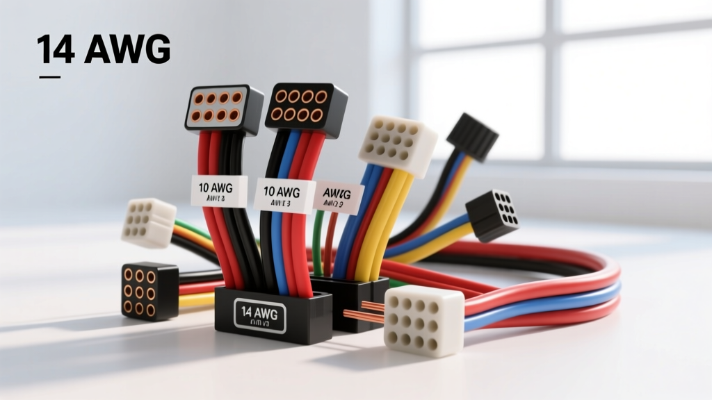
Decoding the Wire Gauge Meaning in Automotive Electrical Systems
When enthusiasts and technicians ask about the wire gauge meaning, they are typically trying to understand how the American Wire Gauge (AWG) numbering system correlates to a conductor's current-carrying capacity. In the AWG system, the relationship is inverse: a smaller gauge number indicates a thicker wire with a larger cross-sectional area, capable of handling more amperage with less resistance. For 12-volt and 24-volt automotive applications, misunderstanding this concept is the leading cause of melted harnesses, dim lighting, and catastrophic electrical fires.
Unlike residential solid-core wiring, automotive environments demand flexibility and vibration resistance. According to SAE International J1128 standards, automotive primary wire must be stranded copper, typically insulated with cross-linked polyethylene (GXL, SXL) or thin-wall polyvinyl chloride (TXL). These insulation types offer thin walls, allowing for more copper in the same outer diameter, which is critical when routing through tight firewall grommets, modern engine bays, and crowded dashboards.
The Physics of AWG: Circular Mils and Stranded Construction
To truly grasp the wire gauge meaning, you must understand the unit of measurement known as the circular mil. A circular mil is the area of a circle with a diameter of one mil (one-thousandth of an inch). The AWG system is based on this geometric progression. For example, 10 AWG wire has a cross-sectional area of approximately 10,380 circular mils, while 4 AWG boasts 41,740 circular mils. This massive increase in copper volume is why stepping up just a few gauge sizes drastically reduces electrical resistance and heat generation.
Furthermore, automotive wire utilizes fine-strand or standard-strand copper bunching. A standard 12 AWG automotive wire might contain 19 strands of smaller wire, whereas a flexible welding cable of the same gauge could contain over 60 micro-strands. More strands mean greater flexibility, preventing the copper from work-hardening and snapping under the constant vibration of a vehicle chassis or engine block.
Automotive Wire Gauge Reference & Ampacity Chart
Before cutting any wire, you must match the AWG size to your specific amperage draw and circuit length. The following chart outlines standard chassis wiring limits based on a 12V DC system with a maximum acceptable voltage drop of 3 percent.
| AWG Size | Strand Count | Max Amps (Chassis) | Resistance (Ohms/1000ft) | Max Length @ 10A (12V) | Typical Automotive Application |
|---|---|---|---|---|---|
| 18 AWG | 16 | 16A | 6.39 | 8 ft | LED marker lights, ECU sensor grounds |
| 16 AWG | 19 | 22A | 4.02 | 12 ft | Radio memory, interior dome lights |
| 14 AWG | 19 | 32A | 2.52 | 20 ft | Fuel pumps, horn relays, power windows |
| 12 AWG | 19 | 41A | 1.59 | 32 ft | Headlight high-beam feeds, blower motors |
| 10 AWG | 19 | 57A | 1.00 | 50 ft | Main ECU power feeds, starter solenoid |
| 8 AWG | 19 | 73A | 0.63 | 80 ft | High-amp cooling fans, winch controls |
| 4 AWG | 19 | 126A | 0.25 | 200 ft | Alternator charge wire, main battery feed |
| 1/0 AWG | 19 | 211A | 0.10 | 500 ft | High-output 250A+ alternator upgrades |
Step-by-Step Installation Guide: Sizing, Routing, and Terminating
Understanding the wire gauge meaning is only the first step. Proper installation requires precise execution to ensure the circuit performs safely under thermal and mechanical stress.
Step 1: Calculate the True Voltage Drop
Never size wire based solely on the amp rating of the fuse. You must calculate voltage drop, especially for long runs to the rear of a truck or trailer. Use the formula: Voltage Drop = (2 x Length x Current x Resistance per foot). For example, if you are installing a 10-amp off-road light bar on a Jeep Wrangler JK with a 15-foot run from the battery, using 14 AWG wire (0.00252 ohms/ft) yields a drop of 0.75 volts. This is acceptable for basic lighting. If the run was 30 feet, you would need to step up to 12 AWG to maintain optimal brightness and prevent the relay from chattering due to low coil voltage.
Step 2: Select the Correct Insulation and Color Code
Always use GXL or TXL wire. Avoid cheap PVC wire from hardware stores, as it becomes brittle under hood temperatures exceeding 125 degrees Celsius. Follow standard SAE color codes for consistency: Red for constant 12V positive, Black for chassis ground, Yellow for switched accessory 12V, and Dark Green or Light Blue for specific sensor signals. Using consistent color coding is crucial when troubleshooting with a multimeter years down the road.
Step 3: Professional Terminating and Crimping
Solder is generally discouraged in high-vibration automotive environments because it creates a rigid point that can lead to copper fatigue and wire breakage just above the solder joint. Instead, use high-quality mechanical crimps. For standard Delphi Weather-Pack or Metri-Pack connectors, use an open-barrel crimping tool with a dedicated Delphi die set. Ensure the wire insulation crimp securely grabs the GXL jacket, while the conductor crimp tightly folds the copper strands without cutting them. Always seal the connection with dual-wall, adhesive-lined heat shrink to prevent capillary action from drawing moisture into the harness.
Case Study: Upgrading the Alternator Charge Wire on an LS-Swapped C10
To see the wire gauge meaning in a practical, high-current scenario, consider an LS-engine swap in a classic Chevy C10 utilizing a 220-amp alternator. The factory 10 AWG charge wire is rated for roughly 57 amps. Pushing 220 amps through it will cause extreme voltage drop, severe heat generation, and eventually a dead battery or melted firewall harness.
- The Fix: Upgrade the main charge wire to 1/0 AWG (one-aught) stranded welding cable or SXL automotive wire.
- Termination: Use heavy-duty 3/8-inch copper ring terminals. Strip the 1/0 AWG wire using a specialized cable stripper, insert it into the terminal, and use a hex-indent hydraulic or heavy ratcheting crimper.
- Routing: Route the 1/0 AWG wire away from the exhaust headers. Use Tesa 51036 PET cloth tape to wrap the wire, providing abrasion resistance and a factory OEM look. Secure it to the engine block or frame using Adel clamps every 12 inches.
- Fusing: Install a 250-amp ANL fuse or Mega Fuse within 18 inches of the battery positive terminal to protect the 1/0 AWG wire in the event of a dead short to the chassis.
Real-World Troubleshooting: Symptoms of Incorrect Wire Gauge
If you misinterpret the wire gauge meaning and undersize your wiring, the vehicle will exhibit specific, diagnosable symptoms:
- Dimming Lights at Idle: When the engine drops to 600 RPM and the alternator output decreases, an undersized main power wire will cause a massive voltage drop. Headlights will visibly dim when the cooling fans or A/C compressor clutch engages.
- Relay Chatter or Clicking: Relays require a specific pull-in voltage, usually around 9V to 10V. If a long, undersized 16 AWG wire is feeding a fuel pump relay, the voltage drop under load will cause the relay to rapidly cycle on and off, destroying the relay contacts and starving the engine of fuel.
- Warm or Melting Insulation: If a wire feels warm to the touch after 10 minutes of operation, it is operating beyond its ampacity rating. Use an infrared thermal camera to identify the exact hot spot, disconnect the battery, and upsize the wire by at least two AWG steps.
- ECU Fault Codes: Modern engine control units monitor reference 5V signals. If the ECU ground wire, often 18 or 16 AWG, is undersized or corroded, the return path resistance increases, pushing the sensor ground reference above 0.1V. This triggers phantom O2 sensor or MAF sensor codes that cannot be fixed by replacing the sensors.
Final Verification and Testing
Always perform a loaded voltage drop test after any installation. Connect your multimeter red lead to the battery positive terminal and the black lead to the load positive terminal. Turn the circuit on. A reading above 0.2V indicates excessive resistance, meaning your wire gauge, crimp quality, or connector pins need immediate re-evaluation. For more advanced wiring diagrams and connector pinouts, reference the Painless Performance technical library and your specific factory service manuals.