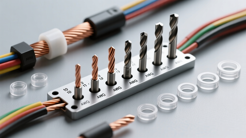
The Critical Intersection of AWG Sizing and Chassis Penetration
When integrating high-current aftermarket systems—such as winch solenoids, secondary lithium battery banks, or high-wattage car audio amplifiers—routing heavy-gauge power cables through the vehicle firewall is an unavoidable necessity. However, a common and catastrophic failure mode occurs when technicians drill an undersized hole, forcing the wire through without a proper grommet, or use an oversized bit that leaves the rubber pass-through loose, allowing water and exhaust gases to enter the cabin. The concept of the wire gauge drill bit matrix is not about drilling the wire itself; rather, it is the precise mathematical correlation between the American Wire Gauge (AWG) size, the outer diameter (OD) of the required protective rubber grommet, and the exact fractional drill bit needed to cut that hole in the chassis.
Modern vehicle firewalls are not simple mild steel sheets. They are often stamped from High-Strength Low-Alloy (HSLA) steel or boron-alloyed steel to meet crash safety standards. Furthermore, primary automotive wire insulated with Cross-Linked Polyethylene (XLPE) has a significantly thicker outer diameter than standard Polyvinyl Chloride (PVC) insulated wire of the same AWG. According to SAE J1128 standards for low-tension primary cable, a 4 AWG XLPE wire can have an OD exceeding 0.35 inches, requiring a much larger pass-through than a standard PVC equivalent. Failing to account for this insulation variance when selecting your drill bit size will result in pinched insulation, exposed copper strands, and a direct short to the chassis—which can trigger an unextinguishable electrical fire in the engine bay.
Master Wire Gauge to Drill Bit Conversion Chart
The following specification chart provides the exact drill bit sizing required for standard automotive rubber firewall grommets. This chart assumes the use of standard EPDM (Ethylene Propylene Diene Monomer) rubber grommets with a Shore A durometer of 60-70, which provides the necessary clamping force to maintain an IP67 environmental seal against dust and water ingress.
| AWG Size | Wire OD (XLPE) | Grommet Inner Dia. | Grommet Outer Dia. | Required Drill Bit (Fraction) | Drill Bit Decimal |
|---|---|---|---|---|---|
| 18 - 14 AWG | 0.09" - 0.11" | 1/4" | 3/8" | 3/8" | 0.375" |
| 12 - 10 AWG | 0.14" - 0.17" | 5/16" | 1/2" | 1/2" | 0.500" |
| 8 AWG | 0.22" - 0.25" | 3/8" | 5/8" | 5/8" | 0.625" |
| 4 AWG | 0.32" - 0.36" | 1/2" | 3/4" | 3/4" | 0.750" |
| 2 AWG | 0.39" - 0.42" | 9/16" | 13/16" | 13/16" | 0.812" |
| 1/0 AWG | 0.46" - 0.50" | 5/8" | 7/8" | 7/8" | 0.875" |
| 2/0 AWG | 0.55" - 0.59" | 3/4" | 1" | 1" | 1.000" |
| 4/0 AWG | 0.70" - 0.75" | 7/8" | 1-1/4" | 1-1/4" | 1.250" |
Note: When routing multiple wires through a single grommet, calculate the combined cross-sectional area of the wires and select a grommet (and corresponding drill bit) where the inner diameter is at least 15% larger than the combined wire bundle diameter to prevent compression damage to the insulation.
Tooling and Metallurgy: Drilling Modern HSLA Firewalls
Using standard black-oxide High-Speed Steel (HSS) twist bits on a modern unibody firewall is a recipe for ruined tooling and jagged, dangerous holes. The localized heat generated by twist bits on HSLA steel quickly dulls the cutting edges, leading to 'walking' and elongated, out-of-round holes. For automotive firewall penetration, M2 Cobalt-coated step bits (often referred to as Unibits) are the mandatory standard.
Step bits offer three distinct advantages for wire gauge routing:
- Self-Deburring Geometry: The stepped flute design naturally shears the inner lip of the sheet metal, leaving a clean, rounded edge that minimizes the risk of slicing through the rubber grommet over time due to engine vibration.
- No Walking: The split-point tip and gradual step-up cutting action prevent the bit from grabbing and tearing the thin (typically 0.8mm to 1.2mm) firewall sheet metal.
- Precision Sizing: The laser-etched steps allow you to stop exactly at the 3/4" or 7/8" mark required for your specific wire gauge drill bit matrix, preventing the oversizing that occurs when a twist bit breaks through the metal and suddenly plunges forward.
After drilling, always treat the bare metal edge with a zinc-rich cold galvanizing spray or an epoxy primer to prevent flash rust, which can degrade the rubber grommet from the outside in. Apply a thin bead of black silicone RTV (Room Temperature Vulcanizing) sealant around the outer lip of the grommet before pressing it into the chassis to ensure a watertight seal against the elements.
Micro Wire Gauge Drill Bits for Terminal Restoration
In the context of automotive electrical diagnostics, the term 'wire gauge drill bit' also refers to the use of precision micro-drill bits and pin gauges for cleaning and sizing female electrical terminals. Over time, moisture intrusion causes galvanic corrosion inside weather-sealed connectors (such as Delphi Weather-Pack, TE AMP, or Bosch Motronic harnesses). This oxidation increases resistance, leading to voltage drops that can trigger phantom sensor codes (e.g., false O2 sensor lean conditions or erratic MAF readings).
When attempting to clean a corroded 0.64mm or 2.8mm female spade terminal, technicians must avoid using standard picks or oversized drill bits that will spread the beryllium copper tension fingers. Once the clamping force of the tension fingers is compromised, the terminal will no longer maintain the necessary micro-wipe action against the male tab, leading to intermittent open circuits under thermal expansion.
Terminal Sizing and Micro-Bit Selection Chart
| Terminal Type | Male Tab Width | Max Allowable Female ID | Cleaning Micro Drill Bit | Wire Gauge Bit Equivalent |
|---|---|---|---|---|
| Micro Timer | 0.60 mm | 0.65 mm | 0.55 mm | #73 (0.024") |
| Standard 0.64mm | 0.64 mm | 0.70 mm | 0.60 mm | #72 (0.025") |
| Mini-Timer 1.2mm | 1.10 mm | 1.20 mm | 1.05 mm | #57 (0.043") |
| Standard 2.8mm | 2.80 mm | 2.95 mm | 2.75 mm | 7/64" (0.109") |
| Heavy Duty 4.8mm | 4.80 mm | 5.00 mm | 4.70 mm | 3/16" (0.187") |
When cleaning these terminals, the micro drill bit should be spun by hand or at very low RPM using a pin vise. The goal is to scrape the copper oxide layer off the internal tension fingers without removing the base beryllium copper material or the optional tin/silver plating. Following mechanical cleaning, the terminal must be flushed with electronic contact cleaner and packed with a dielectric grease (such as Nyogel 760G) to prevent future oxidation while maintaining conductivity through the physical metal-to-metal contact points.
Bulkhead Connectors vs. Single Wire Pass-Throughs
For complex engine swaps or custom chassis builds where multiple sensor and injector circuits must cross the firewall, relying on multiple single wire gauge drill bit holes is structurally unsound and aesthetically poor. Instead, OEMs utilize multi-pin bulkhead connectors. When retrofitting a bulkhead pass-through (such as a 12-pin or 24-pin Deutsch or TE Connectivity circular connector), the drill bit size is dictated by the connector's flange and O-ring seal, not the individual wire gauges inside.
For example, a standard Deutsch DTM 12-pin bulkhead receptacle requires a precise 1.125" (1-1/8") hole saw or step bit notch. The tolerance for this cut is incredibly tight; a hole drilled even 0.020" oversized will compromise the radial O-ring seal, allowing engine bay moisture to wick directly into the cabin-side harness. Always reference the specific TE Connectivity or manufacturer datasheets for bulkhead cutout dimensions before applying a hole saw to the chassis.
Safety Protocols and Harness Protection
Regardless of the wire gauge drill bit size used, the physical routing of the wire post-drilling requires strict adherence to safety protocols. High-amp power wires (4 AWG and larger) should never be routed near sharp suspension components, exhaust headers, or steering shafts. Inside the cabin, the wire must be secured within 6 inches of the firewall grommet using an adhesive-backed P-clamp or a welded chassis stud with a serrated flange nut torqued to 15 Nm to prevent the heavy copper cable from sagging and pulling against the grommet seal.
Furthermore, always install an inline ANL or Class-T fuse within 18 inches of the power source (battery or alternator) on the engine bay side of the firewall. If the wire chafes against the drilled chassis edge due to improper grommet seating or vehicle collision dynamics, the fuse will clear the short circuit in milliseconds, preventing the wire insulation from melting and igniting surrounding acoustic cabin insulation. By strictly adhering to the wire gauge drill bit conversion matrix and utilizing proper step-bit tooling, you ensure a permanent, safe, and factory-grade electrical integration.