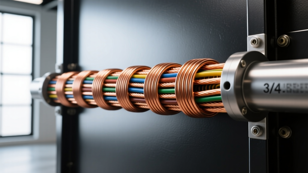
Introduction: EMT Conduit in Extreme Automotive Builds
When most automotive enthusiasts think of wire protection, they picture corrugated split loom, PET braided sleeving, or PVC heat shrink. However, in extreme automotive environments—such as custom EV battery swaps, heavy-duty Cummins diesel conversions, and expedition overland rigs—standard automotive looms simply cannot withstand the abuse. Exhaust radiant heat, rock strikes, rodent intrusion, and high-vibration chassis flex demand a more robust solution. This is where Electrical Metallic Tubing (EMT) or flexible metallic conduit enters the automotive wiring bay.
One of the most common questions we receive from custom chassis builders and EV swap technicians is: how many 10 gauge wires in 3/4 EMT conduit? While this seems like a simple mathematical question, treating an automotive harness like a residential building wire run is a recipe for catastrophic failure. Automotive environments introduce severe ambient temperature fluctuations, complex routing geometries, and high continuous DC loads that drastically alter conduit fill rules and ampacity derating.
This guide provides a step-by-step troubleshooting flow to help you calculate conduit fill, diagnose pull-tension failures, and prevent thermal shutdowns in your custom automotive harnesses.
The Direct Answer: 3/4 EMT Conduit Fill Capacity
To determine the maximum number of 10 AWG wires in a 3/4-inch EMT conduit, we must look at the cross-sectional area. A standard 3/4-inch EMT (Trade Size 21) has an internal diameter of 0.824 inches, yielding a total cross-sectional area of 0.533 square inches. According to the National Electrical Code (NEC) Chapter 9, Table 1, the maximum allowable fill for three or more conductors is 40% of the conduit's internal area, which equals 0.213 square inches.
| Wire Type | Insulation Standard | Outer Diameter (in) | Cross-Sectional Area | Max Wires (40% Fill) |
|---|---|---|---|---|
| 10 AWG THHN/THWN-2 | NEC / UL 83 | 0.184 | 0.0265 sq in | 8 Wires |
| 10 AWG GXL | SAE J1128 | 0.155 | 0.0188 sq in | 11 Wires |
| 10 AWG SXL | SAE J1128 | 0.170 | 0.0227 sq in | 9 Wires |
Note: While SAE GXL wire is thinner and technically allows for 11 wires mathematically, pulling 11 automotive wires through a 3/4-inch metallic conduit without stripping the thin insulation is practically impossible. We recommend a hard limit of 6 to 8 wires for automotive pulls to account for bend radii and pulling tension.
Step-by-Step Troubleshooting Flow: Harness Pull & Heat Failures
When a custom harness routed through EMT conduit fails, it rarely happens immediately. Failures manifest as voltage drops, intermittent shorts to the chassis, or melted insulation near the conduit exits. Use this diagnostic flow to troubleshoot your 10 AWG conduit runs.
Step 1: Diagnose Conduit Fill & Jam Ratios
Symptom: Wires bind, kink, or refuse to pull through the conduit, even when using fish tape and lubricant.
Cause: Ignoring the Jam Ratio. The Jam Ratio is calculated by dividing the conduit's internal diameter by the wire's outer diameter. A jam ratio between 2.8 and 3.2 is notorious for causing single cables to wedge against the conduit wall. While multiple 10 AWG wires shift dynamically, the packing factor in a 3/4-inch EMT can cause a 'logjam' at any 90-degree sweep.
Fix: Limit your 3/4-inch EMT runs to a maximum of six 10 AWG wires if the route includes more than two 90-degree bends. If you must pull eight 10 AWG wires, upgrade to 1-inch EMT (Trade Size 27) to reduce the packing factor and eliminate the jam risk.
Step 2: Troubleshoot Insulation Abrasion & Pull Tension
Symptom: The harness pulls through, but post-pull testing reveals a short to ground. The metallic conduit is conducting current.
Cause: Exceeding the maximum pull tension or using the wrong pulling compound. Automotive SAE GXL wire has a much thinner insulation wall (approx. 0.020 inches) compared to THHN building wire. When pulled around a 90-degree EMT sweep without proper lubrication, the friction strips the GXL insulation, exposing bare copper to the metallic conduit.
Fix:
- Never use standard PVC-based wire pulling lubes on SAE J1128 automotive wire, as they can degrade the cross-linked polyethylene (XLPE) insulation over time.
- Use a high-viscosity, wax-based pulling compound designed for XLPE.
- Attach a pulling eye to the Kevlar aramid yarn filler (if using marine-grade automotive wire) rather than pulling directly on the copper strands, which can stretch the wire and thin the insulation.
Step 3: Evaluate Ampacity Derating & Thermal Shutdown
Symptom: The auxiliary fuel pump or EV cooling fan operates at reduced capacity, or the wire insulation becomes brittle and cracks near the conduit exits after a few months of use.
Cause: Failure to apply NEC ampacity derating factors to the enclosed conduit environment. When multiple current-carrying conductors are bundled inside a sealed metallic tube, they cannot dissipate heat. Furthermore, under-hood ambient temperatures in a diesel or EV swap routinely exceed 104°F (40°C), requiring a secondary temperature correction factor.
Fix: Apply the derating chart below to your 10 AWG harness design.
| Number of 10 AWG Conductors | Base Ampacity (90°C Column) | Derating Factor | Adjusted Ampacity |
|---|---|---|---|
| 1 to 3 Wires | 40 Amps | 100% | 40 Amps |
| 4 to 6 Wires | 40 Amps | 80% | 32 Amps |
| 7 to 9 Wires | 40 Amps | 70% | 28 Amps |
| 10 to 20 Wires | 40 Amps | 50% | 20 Amps |
Critical Automotive Note: Most automotive relays, fuse blocks, and Deutsch connectors are rated for a maximum of 75°C or 85°C. Therefore, your final termination ampacity must be capped at the 75°C column (which is 30A base for 10 AWG) before applying the conduit fill derating factor. If you pull six 10 AWG wires through 3/4-inch EMT, your true safe continuous load is 24 Amps (30A x 80%).
Real-World Application: Overland Auxiliary & EV Cooling Harness
Let us apply this data to a real-world scenario. You are building an expedition overland rig with a custom auxiliary harness routed through 3/4-inch flexible metallic conduit along the chassis rail to protect it from brush and rock strikes. The harness powers a high-output auxiliary water pump and a heavy-duty winch contactor.
Harness Pinout and Color Code
- Wire 1 (Red): 10 AWG SXL - Auxiliary Water Pump +12V Power (30A Max Draw)
- Wire 2 (Black): 10 AWG SXL - Auxiliary Water Pump Ground
- Wire 3 (Yellow): 10 AWG SXL - Winch Contactor Trigger Signal
- Wire 4 (White): 10 AWG SXL - Winch Contactor Ground Reference
Connector Specifications
At the termination points, the harness breaks out of the EMT conduit and transitions into a Deutsch DT 4-Pin Connector (Part # DT04-4P).
- Pin 1: Red Wire (Pump Power)
- Pin 2: Black Wire (Pump Ground)
- Pin 3: Yellow Wire (Contactor Trigger)
- Pin 4: White Wire (Contactor Ground)
Best Practices for EMT in Automotive Environments
If you are committing to using 3/4-inch EMT or flexible metallic conduit for your 10 AWG automotive harness, follow these expert installation rules:
- Deburr the Ends: EMT conduit is cut with a hacksaw or band saw, leaving razor-sharp metal burrs on the inner edge. You must use a dedicated conduit reamer to smooth the inner lip. A single missed burr will slice through 10 AWG SXL insulation the moment the vehicle experiences chassis flex.
- Use Anti-Short Bushings: Also known as 'red heads', these plastic bushings snap into the cut ends of the EMT. They provide a smooth, insulated transition zone where the automotive wires exit the metal tube and enter the engine bay or battery enclosure.
- Ground the Conduit: Metallic conduit must be bonded to the vehicle chassis. Use a copper grounding strap and a star washer to bite through the paint and bond the conduit to a clean, bare metal chassis point. This ensures that if a 10 AWG wire does chafe and short, the conduit safely routes the fault current to the battery negative, blowing the main fuse rather than energizing the vehicle's exterior body panels.
- Seal the Ends: Engine bays and undercarriages are full of water, oil, and road grime. Use a marine-grade adhesive-lined heat shrink (like 3M MDT) or a silicone conduit sealant at both ends of the EMT run to prevent the conduit from filling with water, which would accelerate galvanic corrosion between the copper wire and the steel conduit.
Conclusion
Answering the question of how many 10 gauge wires fit in 3/4 EMT conduit requires more than just a glance at a fill chart. While the mathematical limit is eight to eleven wires depending on the insulation type, the practical automotive limit is six wires to account for pull tension, jam ratios, and severe ampacity derating. By treating your conduit runs with the same respect as high-voltage EV cabling, and by strictly following SAE and NEC derating guidelines, you can build a custom harness that will survive the harshest off-road and track environments.