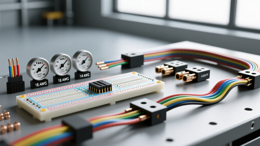
The Intersection of Electronics Prototyping and Automotive Wiring
When developing custom automotive circuits—such as ECU bench testers, sensor simulators, or auxiliary switch panel logic—the term breadboard wire gauge typically refers to the 22 AWG solid-core jumpers used in standard electronics prototyping. However, bridging the gap between a controlled bench environment and the harsh, high-vibration reality of a vehicle chassis requires a strict understanding of wire specifications, ampacity derating, and material science. At Autoflowwire, we treat automotive prototyping not as a hobby, but as the first critical phase of harness engineering.
Standard Breadboard Wire vs. Automotive Grade
Standard breadboard wire is almost exclusively 22 AWG (0.64mm diameter) solid copper with thin PVC insulation. While excellent for rigid, low-current logic circuits on a solderless breadboard, solid-core wire is catastrophically prone to work-hardening and fracture under automotive vibration. Furthermore, standard PVC insulation melts at lower temperatures and lacks the fluid resistance required under the hood.
For automotive prototyping that will eventually transition into a vehicle, engineers must adapt the "breadboard gauge" concept to stranded, cross-linked automotive wire. The closest automotive equivalent to standard breadboard wire is 22 AWG TXL or GXL stranded wire, though 18 AWG is often the practical minimum for reliable crimping into standard automotive connector cavities.
Breadboard Wire Gauge Specifications & Ampacity Chart
The following reference chart compares standard electronics breadboard wire with its automotive-grade counterparts, factoring in the SAE J1128 derating requirements for high-temperature environments like engine bays.
| Wire Type | AWG Size | Conductor Type | Insulation | Max Amps (Cabin 40°C) | Max Amps (Engine Bay 125°C) |
|---|---|---|---|---|---|
| Standard Jumper | 22 AWG | Solid Core | PVC | 7.0A | Not Rated (Melts/Degrades) |
| Automotive TXL | 22 AWG | Stranded (19/34) | Cross-linked PVC | 9.0A | 4.5A (Derated 50%) |
| Automotive GXL | 20 AWG | Stranded (19/32) | Cross-linked PVC | 11.0A | 6.0A (Derated) |
| Automotive SXL | 18 AWG | Stranded (19/30) | Cross-linked PVC | 16.0A | 10.0A (Derated) |
Note: Ampacity ratings are based on single wires in free air per SAE J1128 standards. Bundled wires require further derating of 20-30%.
Transitioning from Breadboard to Automotive Harness
A common failure point in custom automotive electronics occurs during the transition from the prototyping phase to the final harness. The physical dimensions of breadboard wire gauge create significant mating challenges with automotive connectors.
Pin Configurations and Connector Adaptations
Standard automotive connectors, such as the Molex MX150 or TE Connectivity AMP Superseal 1.5, are engineered for specific wire insulation diameters and strand counts to ensure the waterproof seal (blind plug or wire seal) compresses correctly.
- 22 AWG Solid Core (Breadboard): Will not properly engage the silicone wire seal on a Superseal 1.5 connector. The solid wire is too rigid, and the insulation diameter is often too narrow, leading to moisture ingress and immediate corrosion.
- 22 AWG TXL Stranded: Requires specific "small cavity" or "reduced diameter" seals (often colored yellow or grey depending on the manufacturer) to prevent pushing the seal out of the connector housing during insertion.
- 18 AWG GXL Stranded: The ideal bridge. It carries the low-current signals typical of breadboard logic (like 5V reference voltages or Hall-effect sensor returns) but possesses the physical bulk required for standard red or black automotive wire seals.
Real-World Failure Modes in Prototyped Auto Circuits
When engineers use literal breadboard wire in automotive test mules, we consistently document three specific failure modes in the field:
- Vibration-Induced Fracture: Solid-core 22 AWG wire work-hardens rapidly when subjected to the 20-200Hz vibration profile of a vehicle chassis. Fractures typically occur exactly at the crimp barrel or solder joint, resulting in intermittent open circuits that are notoriously difficult to diagnose with a standard multimeter.
- Insulation Shrinkback: Standard PVC breadboard wire insulation shrinks when exposed to the ambient 100°C+ heat of an engine bay. This exposes bare copper inside the connector cavity, leading to short-to-ground against the connector housing or adjacent pins.
- Galvanic Corrosion: Bare copper solid wire lacks the tinning or silver-plating found in automotive-grade stranded wire (per TE Connectivity automotive specifications). When exposed to high humidity and road salts, the capillary action of stranded wire can wick moisture, but solid wire oxidation creates a high-resistance diode effect at the crimp, skewing low-voltage sensor data (e.g., O2 sensor or MAF signals).
Voltage Drop Calculations for Prototyped Sensor Circuits
One of the most critical errors made when translating breadboard prototypes to automotive harnesses is ignoring voltage drop over distance. A 5V reference signal from an ECU to a MAP (Manifold Absolute Pressure) sensor is highly sensitive to resistance. Standard 22 AWG breadboard wire has a resistance of approximately 16.14 ohms per 1,000 feet. While negligible on a 4-inch breadboard, this becomes a massive issue in a full vehicle harness.
Consider a custom turbocharged build using a 3-bar MAP sensor. If the 5V reference and sensor ground are run using 22 AWG wire over a 20-foot round trip to the cabin-mounted ECU, the voltage drop can easily exceed 0.15V under load. This skew causes the ECU to read lower boost pressure than actual, leading to dangerous over-boosting and detonation.
Mitigation Strategies for Long-Run Prototyping
- Upsize the Reference and Ground: Always use 18 AWG or 16 AWG GXL wire for the 5V reference and sensor ground circuits, reserving 20-22 AWG strictly for the high-impedance signal return wire.
- Shielded Twisted Pair (STP): For crank and cam position sensors, which output low-amplitude AC or Hall-effect square waves, standard breadboard wire will act as an antenna for alternator whine and ignition RFI. You must transition to shielded twisted pair (STP) automotive cable, grounding the shield at the ECU pin only.
Crimping Techniques for Small-Gauge Automotive Wire
Adapting breadboard-gauge wire to automotive terminals requires precision tooling. Standard ratcheting crimpers designed for 14-10 AWG battery cables will crush and destroy the micro-terminals used for 22-18 AWG sensor wires.
For Molex MX150 and Deutsch DT series contacts in the 20-22 AWG range, you must use a precision four-indent crimping tool (such as the TE Connectivity CERTI-CRIMP or equivalent). The crimp profile must secure the wire strands in the conductor crimp wings while simultaneously folding the insulation wings around the wire jacket. If the insulation crimp is too tight, it will cut through the thin cross-linked PVC of TXL wire, creating a stress riser that guarantees wire failure under vibration.
Best Practices for ECU Bench Testing and Sensor Simulation
If you are building a bench harness to simulate vehicle sensors for ECU tuning or diagnostics, you must mimic the exact resistance and voltage drop of the production vehicle harness. While a 6-inch piece of 22 AWG breadboard wire has negligible resistance (approx. 0.009 ohms), a 15-foot run of 18 AWG automotive wire to a rear O2 sensor introduces measurable voltage drop.
Expert Recommendation: When prototyping on a solderless breadboard, use standard 22 AWG jumpers for logic and ground returns. However, for any circuit carrying injector pulse signals, ignition coil dwell currents, or 5V reference supplies, bypass the breadboard entirely. Use a dedicated terminal block with 16 AWG TXL wire to handle the transient inductive kickback (which can exceed 60V) without arcing across the breadboard's internal leaf springs.