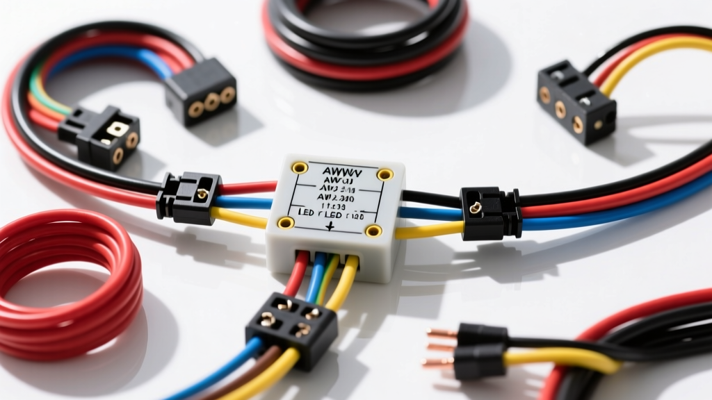
Complete Wiring Diagram Walkthrough: Auxiliary LED Light Bar Harness
When upgrading a truck, Jeep, or overland rig with auxiliary lighting, selecting the correct LED wire gauge is the most critical step in preventing electrical fires and ensuring maximum lumen output. Unlike traditional incandescent or halogen bulbs, high-performance LED light bars (such as those from Baja Designs or Rigid Industries) draw significantly less steady-state current. However, they contain massive internal capacitor banks that create severe inrush currents upon startup. Misjudging your LED wire gauge based solely on steady-state amperage is a primary cause of melted relay sockets and premature harness failure.
In this complete wiring diagram walkthrough, we will deconstruct a standard 4-pin Bosch-style relay harness used for automotive LED auxiliary lighting. We will map the exact AWG requirements, wire insulation types, connector specifications, and pinout configurations necessary for a safe, OEM-grade installation.
Wire Insulation Standards: SAE J1128 vs. Building Wire
Before routing any wires, you must select the correct insulation type. Never use THHN building wire in an automotive application. THHN is stiff, prone to cracking under engine bay vibration, and lacks the chemical resistance required to survive oil, coolant, and road salt exposure. Instead, you must use cross-linked polyethylene (XLPE) automotive wire that meets the SAE J1128 standard.
- GXL (General Cross-Linked): Standard wall thickness. Ideal for general harness routing and relay pigtails.
- TXL (Thin Cross-Linked): Thinner insulation, highly flexible. Best for tight firewall grommets and dashboard switch panels.
- SXL (Special Cross-Linked): Thickest insulation. Reserved for high-heat areas near exhaust manifolds or turbochargers.
Phase 1: The High-Current Power Feed (Pin 30)
Pin 30 on a standard ISO 7588-1 (Bosch) 4-pin relay is the main power input directly from the vehicle battery. This circuit must handle both the continuous amperage of the LED bar and the initial inrush spike.
Gauge Selection and Fusing
For a standard 200W LED light bar, the steady-state draw is approximately 16.6 Amps (200W / 12V). However, the inrush current can momentarily exceed 40 Amps as the internal capacitors charge. Using 14 AWG wire here will result in severe voltage drop and potential thermal meltdown at the relay spade terminal.
- Under 10 Feet (Battery to Relay): Use 12 AWG GXL wire.
- 10 to 20 Feet: Step up to 10 AWG GXL wire to mitigate voltage drop.
- Over 20 Feet: Use 8 AWG GXL wire.
Fuse Sizing: The fuse must be located within 6 inches of the battery positive terminal. For a 12 AWG feed wire, use a 20A or 25A ATO/ATC blade fuse. For 10 AWG wire, use a 30A Maxi-fuse or a 40A ANL fuse if running multiple high-wattage bars.
Phase 2: The Load Circuit (Pin 87 to LED Bar)
Pin 87 is the normally open (NO) output that sends power to the LED light bar when the relay coil is energized. The wire gauge here should match or exceed the gauge used on Pin 30.
Connector Specifications: The Deutsch DT Standard
Do not use generic spade connectors or twist-on weather-proof caps for the final connection to the light bar. The off-road industry standard is the TE Connectivity Deutsch DT series 2-pin connector. These connectors feature silicone rear wire seals and a thermoplastic wedge lock that prevents terminal back-out under extreme vibration.
- Wire Range: 14 AWG to 16 AWG (If your main harness is 12 AWG, use a sealed butt-splice with adhesive-lined heat shrink to step down to 14 AWG for the Deutsch pins).
- Crimping Tool: Use a precision Deutsch crimp tool (e.g., TE DT-CT-001) to ensure the wire crimp and insulation crimp are properly formed without damaging the nickel-plated copper contacts.
Phase 3: The Trigger Circuit (Pin 86)
Pin 86 is the low-current trigger input. This wire connects to your cabin switch, OEM upfitter switch, or high-beam headlight tap. Because the relay coil typically draws less than 0.2 Amps, heavy-gauge wire is unnecessary and makes routing through the firewall grommet difficult.
- Recommended Gauge: 18 AWG TXL wire.
- Tapping OEM Circuits: If tapping into an existing headlight or DRL circuit to trigger the relay, use a Posi-Tap connector or solder-and-heat-shrink method. Never use 3M Scotch-Loks, as they cut through the OEM wire strands, creating a high-resistance point that will corrode and fail.
Phase 4: Grounding Strategy (Pin 85)
Pin 85 completes the relay coil circuit to ground. A poor ground is the number one cause of relay chatter (rapid clicking) and flickering LEDs.
- Recommended Gauge: 18 AWG TXL (matching the trigger wire).
- Termination: Use a heat-shrink, adhesive-lined ring terminal.
- Chassis Prep: Sand the grounding point down to bare, shiny metal. Coat the terminal with dielectric grease after torquing to spec (typically 15-20 Nm for an M8 chassis bolt) to prevent galvanic corrosion.
Standard 4-Pin Relay Pinout Reference Table
| DIN / ISO Pin | Relay Function | Wire Color (Standard) | AWG Size | Connection Point |
|---|---|---|---|---|
| 30 | Common / Power Input | Red | 10 - 12 AWG | Battery Positive (+) via Fuse |
| 87 | Normally Open (NO) Output | Blue or White | 10 - 14 AWG | LED Light Bar Positive (+) |
| 86 | Coil Positive (+) Trigger | Yellow or Green | 18 AWG | Cabin Switch / Upfitter Switch |
| 85 | Coil Negative (-) Ground | Black | 18 AWG | Chassis Ground / Battery (-) |
LED Wattage to AWG Sizing & Fusing Chart
Use this reference chart to determine the correct LED wire gauge and fuse size based on the total wattage of your lighting setup and the length of the main power run (Pin 30 to Pin 87).
| Total LED Wattage | Steady Draw (A) | Est. Inrush (A) | AWG (< 10 ft) | AWG (10 - 20 ft) | Fuse Size |
|---|---|---|---|---|---|
| 50W - 100W | 4.1 - 8.3A | 15A | 14 AWG | 12 AWG | 15A ATO |
| 120W - 200W | 10.0 - 16.6A | 35A | 12 AWG | 10 AWG | 20A ATO / 30A Maxi |
| 240W - 300W | 20.0 - 25.0A | 50A | 10 AWG | 8 AWG | 30A Maxi / 40A ANL |
| 400W+ | 33.3A+ | 80A+ | 8 AWG | 6 AWG | 60A ANL |
Advanced Troubleshooting: CAN-Bus, PWM, and Voltage Drop
The CAN-Bus and PWM Strobe Effect
Modern vehicles (2018+ F-150, 2019+ Ram 1500, JL/JT Wranglers) utilize Pulse Width Modulation (PWM) and CAN-bus multiplexing to control exterior lighting and upfitter switches. PWM rapidly cycles the voltage on and off to dim lights or monitor bulb health. Because LEDs draw so little current and react instantly to voltage changes, connecting an LED bar directly to a PWM-controlled OEM switch will cause the light bar to strobe or flicker violently.
The Fix: You must install a PWM filter module or a solid-state relay isolator between the OEM trigger wire and Pin 86 of your harness. The 18 AWG trigger wire will carry the PWM signal to the filter, which smooths the signal into a steady 12V DC output before it hits the relay coil.
Calculating Voltage Drop
If your LED bar appears dim or shifts from a cool 6000K white to a yellowish hue under load, you are experiencing severe voltage drop. The formula for single-phase DC voltage drop is:
VD = 2 × L × I × R
- L = One-way length of the wire in feet.
- I = Current in Amps.
- R = Resistance per foot of the specific AWG wire (e.g., 12 AWG copper is approximately 0.001588 Ω/ft at 20°C).
For a 200W (16.6A) light bar using 15 feet of 12 AWG wire: VD = 2 × 15 × 16.6 × 0.001588 = 0.79 Volts. A 0.79V drop is acceptable (less than 3% of a 12V system). However, if you used 16 AWG wire (R = 0.004016 Ω/ft), the drop would be 2.0 Volts, pushing the system below the optimal operating voltage of the LED drivers and triggering internal low-voltage protection shutoffs.
Summary and Best Practices
Mastering your LED wire gauge selection goes far beyond simply matching amperage to a generic chart. By accounting for inrush currents, utilizing SAE J1128 cross-linked wiring, terminating with Deutsch DT connectors, and respecting the nuances of modern CAN-bus PWM systems, you ensure your auxiliary lighting operates reliably in the harshest environments. Always verify your specific vehicle's upfitter guidelines—such as those found in Painless Performance wiring manuals or OEM body builder books—before tapping into factory circuits.