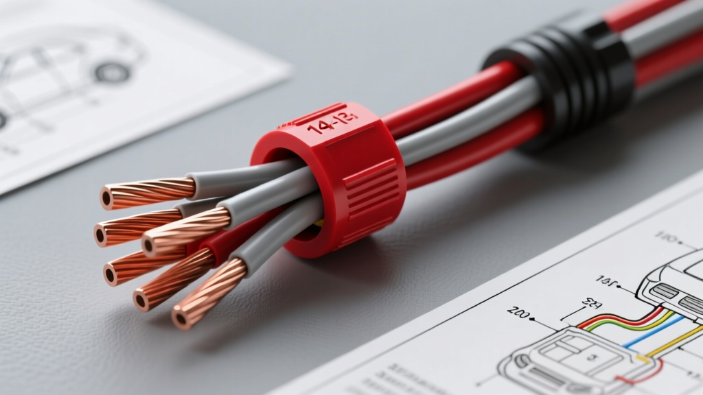
The Direct Answer: 14 AWG Capacity in a Red Wire Nut
When automotive DIYers, off-road builders, and classic car restorers ask how many 14 gauge wires in a red wire nut can safely be connected, the answer depends heavily on the wire construction. For standard household solid-core copper, a red wire nut might accommodate up to four 14 AWG wires. However, automotive electrical systems exclusively use finely stranded wire. Based on manufacturer specifications for standard red twist-on connectors (such as the Ideal 73B or WingNut Red), the absolute maximum capacity for 14 AWG stranded automotive wire (SAE J1128 GXL or TXL) is three (3) wires.
Attempting to force four 14 AWG stranded wires into a red wire nut over-stresses the internal steel coil spring. This causes the spring to deform, resulting in inadequate bite force on the copper strands. In a stationary household wall, this might merely cause a minor resistance increase. In a vehicle subjected to chassis vibration and thermal cycling, a four-wire 14 AWG red wire nut splice will inevitably vibrate loose, leading to arcing, voltage drop, or a localized electrical fire.
Wiring Diagram Walkthrough: The Auxiliary Lighting Relay Circuit
To understand why this limitation matters, let us walk through a complete wiring diagram for a common automotive modification: a 4x4 auxiliary LED light bar harness utilizing a standard Bosch-style ISO Mini Relay. In this schematic, you are managing multiple circuits that require splicing.
Diagram Pinout and Wire Routing
- Pin 30 (12V+ Battery Feed): Requires 10 AWG wire (Red) protected by a 30A inline ATC fuse.
- Pin 87 (Load Output to Lights): Requires 14 AWG wire (Red) to handle the 15A draw of the LED bar.
- Pin 86 (Switched Trigger): Requires 18 AWG wire (Blue) routed to the cabin toggle switch.
- Pin 85 (Relay Coil Ground): Requires 14 AWG wire (Black) routed to the chassis.
The critical junction occurs at the grounding point. If you are wiring a triple-light setup (e.g., a main light bar and two ditch lights), you will have three separate 14 AWG black ground wires that need to be spliced together before terminating at a single M8 chassis ring terminal. This is the exact moment a builder typically reaches for a red wire nut. According to the Littelfuse Mini ISO Relay datasheet, the coil ground must maintain a near-zero resistance path to ensure the relay switches instantly and prevents back-EMF voltage spikes. A compromised three-wire or four-wire twist-on splice will introduce resistance, delaying relay engagement and generating excess heat.
The Failure Mode: Why Wire Nuts Violate Automotive Standards
Automotive wiring operates under extreme environmental duress. The SAE J1128 standard dictates that low-tension primary cables must withstand continuous temperatures up to 125°C (257°F) for GXL wire, alongside exposure to battery acid, road salt, and constant high-frequency vibration.
Twist-on wire nuts fail in these environments for three specific reasons:
- Insulation Interference: Automotive GXL/TXL wire features a thin-wall, hard cross-linked polyethylene insulation. Unlike the soft PVC of THHN house wire, GXL insulation is rigid. When twisted into a wire nut, the rigid insulation often binds against the plastic cap before the copper strands are fully seated into the steel spring.
- Thermal Expansion Mismatch: Under-hood temperatures cycle from sub-zero winter mornings to over 200°F near the exhaust headers. The plastic shell of the wire nut and the copper wires expand and contract at different rates. Over hundreds of thermal cycles, this "pumping" action pushes the wires out of the spring grip.
- Strand Deformation: 14 AWG automotive wire typically consists of 19 strands of 0.0253-inch copper. The aggressive teeth of a wire nut spring are designed to bite into solid wire or coarse 7-strand wire. On 19-strand wire, the spring often cuts or shears the outer strands, reducing the effective cross-sectional area and increasing resistance.
Specification Chart: Wire Nut vs. Automotive Connectors
When executing your wiring diagram, you must replace the red wire nut with an automotive-grade equivalent capable of handling a multi-wire 14 AWG splice. Below is a technical comparison of splicing methods for joining three 14 AWG wires.
| Connector Type | Max 14 AWG Stranded Capacity | Vibration Resistance | Moisture Sealing (IP Rating) | SAE / OEM Compliance |
|---|---|---|---|---|
| Standard Red Wire Nut | 3 Wires (Marginal) | Very Poor | None (IP00) | Non-Compliant |
| Adhesive-Lined Heat Shrink Crimp Cap | 3 to 4 Wires | Excellent | IP67 (Waterproof) | Compliant |
| Solder Seal Sleeve (e.g., Raychem) | 2 to 3 Wires | Good (if strain relieved) | IP68 (Submersible) | Compliant |
| Open Barrel Crimp Splice (Taped) | 3 Wires (Requires specific die) | Excellent | IP54 (Depends on tape) | OEM Standard |
Step-by-Step: Executing the 3-Way 14 AWG Splice the Right Way
To properly ground the three 14 AWG wires from our relay diagram walkthrough without using a red wire nut, you should utilize an adhesive-lined (dual-wall) heat shrink crimp cap. Follow these precise steps to ensure a waterproof, vibration-proof connection.
- Strip the Wires: Using a precision wire stripper, remove exactly 3/8-inch (9.5mm) of insulation from the ends of all three 14 AWG black ground wires. Do not nick the 19 copper strands; a nicked strand creates a stress riser that will snap under engine vibration.
- Align the Conductors: Hold the three stripped ends perfectly parallel. Do not twist them together with pliers. Twisting the wires before crimping creates an uneven bundle that will not compress correctly inside the crimp barrel.
- Insert into the Crimp Cap: Slide the parallel wires into the metal barrel of a 14-16 AWG (typically blue-colored) adhesive-lined crimp cap. Ensure all 57 total strands (19 per wire x 3 wires) are fully inserted and none are folded back over the insulation.
- Execute the Crimp: Use a ratcheting crimp tool equipped with a 1.5mm² or 16-14 AWG hex-indent die. Position the tool squarely over the metal barrel and squeeze until the ratchet releases. The hex indent forces the copper strands into a solid, cold-welded mass, eliminating all air pockets.
- Apply Heat for Sealing: Using a heat gun set to approximately 300°F (150°C), apply heat evenly to the polyolefin shrink tubing. Start from the middle and work your way out to the edges. You must see the hot-melt adhesive bubble slightly out of the ends of the tube. This confirms the moisture seal is complete, preventing capillary action from drawing water into the harness.
Troubleshooting Multi-Wire Splice Voltage Drop
If you have inherited a vehicle wiring harness where a previous owner used red wire nuts to splice multiple 14 AWG wires, you must proactively diagnose and replace them before a failure occurs. Use a digital multimeter (DMM) to perform a voltage drop test.
Set your DMM to DC Volts. Place the black probe on the negative battery terminal and the red probe on the wire side of the splice (past the wire nut) while the circuit is under load (e.g., the auxiliary lights are turned on). A healthy, properly crimped 14 AWG splice will show a voltage drop of less than 0.05V. If your meter reads a voltage drop greater than 0.2V across the wire nut splice, the internal spring has failed, and the connection is generating excess heat. Furthermore, inspect the plastic shell of the wire nut. If the plastic feels brittle, shows brown scorch marks, or emits a faint ozone smell, the splice is actively arcing internally and must be cut out and replaced with an adhesive-lined crimp cap immediately.