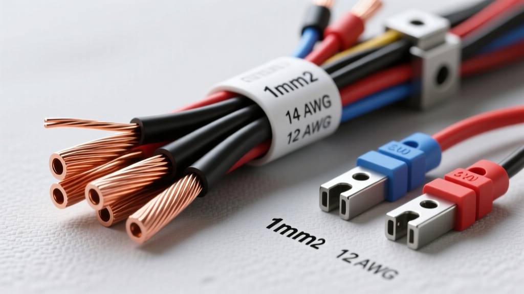
The Metric vs. SAE Dilemma in Automotive Wiring
When executing complex automotive modification projects—such as custom EFI harnesses, engine swaps, or auxiliary sensor integrations—builders frequently encounter a frustrating discrepancy between metric and SAE wire sizing. Modern OEM harnesses, particularly those from Bosch, Continental, and Denso, rely heavily on the metric standard. The 1mm wire gauge (properly designated as 1.0mm² cross-sectional area) is a foundational conductor size in these systems. However, many aftermarket suppliers and local auto parts stores only stock AWG (American Wire Gauge) equivalents. Misunderstanding the relationship between 1mm² wire and its AWG counterpart can lead to improper terminal selection, increased voltage drop, and catastrophic harness failures in high-temperature engine bays.
This comprehensive reference guide breaks down the exact specifications, ampacity ratings, and practical application strategies for utilizing 1mm wire gauge in your next automotive upgrade project. Whether you are extending a wideband O2 sensor or repinning an aftermarket ECU, understanding the physical and electrical properties of this specific wire size is non-negotiable for professional-grade results.
1mm² vs. AWG: The Conversion Reality
A common and dangerous mistake in the modding community is assuming that 1mm wire gauge is equivalent to 1 AWG. This is entirely false. The metric designation refers strictly to the cross-sectional area of the copper strands in square millimeters. In the SAE AWG system, wire is sized by diameter and geometric progression. The closest standard AWG equivalent to 1.0mm² is 17 AWG for highly flexible stranded wire, though many manufacturers round this to 18 AWG for general chassis wiring applications.
While 18 AWG has a cross-sectional area of roughly 0.823mm², true 1.0mm² wire contains approximately 21% more copper. This difference drastically alters the current-carrying capacity (ampacity) and the physical crimp cavity required for connectors. Using an 18 AWG terminal on a true 1.0mm² metric wire will result in copper strand shearing or insulation crushing, leading to high-resistance cold joints.
Technical Specification Chart: 1mm Wire Gauge
| Specification | Metric (1.0mm²) | SAE Equivalent (18 AWG) |
|---|---|---|
| Cross-Sectional Area | 1.00 mm² | 0.823 mm² |
| Strand Count (Typical) | 32 x 0.20mm | 16 x 0.25mm |
| Nominal Copper Diameter | 1.13 mm | 1.02 mm |
| Resistance @ 20°C (per ft) | 5.08 mΩ/ft | 6.39 mΩ/ft |
| Resistance @ 20°C (per m) | 16.7 mΩ/m | 20.9 mΩ/m |
| Max Ampacity (Single Wire in Free Air) | 11A - 14A | 9A - 11A |
Insulation Types and Temperature Derating
The copper gauge is only half the equation; the insulation dictates the wire's survival in an engine bay. For 1mm wire gauge applications, you must select insulation that complies with SAE J1128 or ISO 6722 standards. The three most common automotive insulation types are:
- TXL (Thin-wall Cross-linked): The gold standard for custom ECU harnesses. It offers excellent heat resistance up to 125°C and has a very thin outer wall, allowing you to pack more 1mm circuits into a tight Deutsch or AMPSEAL connector backshell.
- GXL (General-wall Cross-linked): Slightly thicker than TXL, offering better abrasion resistance for harnesses routed along the chassis or firewall.
- SXL (Special-wall Cross-linked): The thickest insulation, rarely used for 1mm signal wires, but reserved for heavier gauge power circuits.
- Pin 1 (Calibration Resistor): White wire. Requires 1.0mm² (or 0.75mm²). This is a highly sensitive reference circuit. Do not use thicker wire, as terminal insertion force can damage the sensor PCB.
- Pin 2 (Nernst Cell Signal): Grey wire. Requires 1.0mm². High impedance; highly susceptible to EMI. Must be kept away from ignition coils.
- Pin 3 (Heater +): Red wire. Requires 1.5mm² (16 AWG). The heater circuit draws up to 3A on cold start. Using 1mm wire gauge here will cause voltage drop and slow sensor light-off times.
- Pin 4 (Heater -): Black wire. Requires 1.5mm² (16 AWG).
- Pin 5 (Pump Cell +): Yellow wire. Requires 1.0mm².
- Pin 6 (Pump Cell -): Blue wire. Requires 1.0mm².
- Strip exactly 4.0mm to 5.0mm of insulation from the 1mm wire. Do not nick the outer copper strands.
- Verify that all strands are twisted tightly and inserted fully into the terminal wire barrel. No 'birdcaging' or stray strands outside the crimp zone.
- The insulation crimp must grip the TXL jacket firmly without piercing through to the copper.
- Perform a visual inspection: the wire strands should be visible just past the end of the wire barrel (the 'bellmouth' effect) to confirm full insertion depth.
Furthermore, ampacity must be derated when wires are bundled. According to SAE guidelines, if your 1mm wire gauge is part of a 15-circuit harness wrapped in corrugated loom and Tesa tape, the continuous current capacity drops by nearly 40%. A wire rated for 12A in free air may only safely carry 7A inside a dense, under-hood bundle.
Project Application 1: Bosch LSU 4.9 Wideband Sensor Extension
One of the most frequent upgrade projects requiring precise 1mm wire gauge utilization is extending a Bosch LSU 4.9 wideband O2 sensor. The LSU 4.9 utilizes a specialized 6-pin connector, and mixing up the wire gauges or colors will instantly destroy the sensor's internal calibration resistor or the ECU's wideband controller.
LSU 4.9 Pinout and Wire Sizing Strategy
When extending this harness, splice the 1mm wire gauge signal lines using adhesive-lined heat shrink (such as 3M or Qualtek) and solder the joints. Never use butt connectors in wideband signal circuits, as the mechanical crimp can introduce micro-resistances that skew the air/fuel ratio reading by up to 0.5 AFR.
Project Application 2: Aftermarket ECU Sensor Pigtails
When wiring an aftermarket ECU like a Haltech Elite or AEM Infinity, builders must create custom sensor pigtails for the MAP (Manifold Absolute Pressure), TPS (Throttle Position Sensor), and IAT (Intake Air Temperature) sensors. These sensors typically operate on a 5V reference, a sensor ground, and a 0-5V signal return.
The TE Connectivity Superseal 1.5 series is the industry standard for these connections. For the 1mm wire gauge, you must use the specific TE terminal part number 280590-1 (designed for 0.5mm² to 1.0mm²). Attempting to force a 1.5mm² terminal into the Superseal cavity with 1mm wire will result in a loose fit, leading to terminal fretting corrosion and intermittent 5V reference failures. Always use a ratcheting crimping tool, such as the Rennsteig 624 000 3, to ensure the wire barrel and insulation barrel are compressed to exact factory tolerances.
Crimping, Tooling, and Pull-Test Standards
A proper crimp on a 1mm wire gauge terminal requires a precise balance of compression. If the crimp is too loose, resistance increases, generating heat and melting the connector housing. If the crimp is too tight, the copper strands are severed, reducing the effective cross-sectional area and creating a mechanical weak point.
According to IPC/WHMA-A-620 standards for automotive cable assemblies, a properly crimped 1.0mm² wire must withstand a minimum pull force of 15 lbs (67 Newtons) before the wire breaks or pulls out of the terminal barrel. To achieve this:
Voltage Drop Calculations and Troubleshooting
Voltage drop is the silent killer of automotive modifications. Because 1mm wire gauge has a resistance of roughly 5.08 mΩ per foot, long harness runs can degrade critical sensor signals. Let us calculate the voltage drop for a custom IAT sensor harness running 12 feet from the ECU to the intake manifold.
Formula: Voltage Drop = Current (I) x Resistance (R)
Total Wire Length: 12 feet out + 12 feet back (ground loop) = 24 feet.
Total Resistance: 24 ft x 0.00508 Ω/ft = 0.121 Ω.
Current Draw: An IAT sensor (thermistor) typically draws less than 10mA (0.01A).
Calculation: 0.01A x 0.121 Ω = 0.00121 Volts (1.21 mV).
In this scenario, the 1.21 mV drop is entirely negligible and will not affect the ECU's temperature calculation. However, if that same 1mm wire gauge is mistakenly used to power a 2A fuel pump relay coil or an idle air control (IAC) valve solenoid, the math changes drastically. At 2A, the voltage drop over 24 feet becomes 0.242 Volts. While still functional, the power dissipated as heat in the wire (P = I²R) increases, which can degrade TXL insulation over time if routed near exhaust headers.
Troubleshooting Tip: If your ECU is throwing intermittent 'Sensor Open Circuit' codes, use a digital multimeter to perform a voltage drop test across the harness connector while the circuit is under load. Any reading above 50mV on a 1mm signal wire indicates a failing crimp, terminal corrosion, or an undersized wire application. For deeper diagnostic protocols and harness repair standards, refer to the Pacer Group Technical Center documentation on automotive circuit testing.
Summary of Best Practices
Mastering the 1mm wire gauge is essential for any serious automotive electrical modifier. Always verify whether your schematic calls for metric cross-section or AWG. Stock high-quality TXL insulated 1.0mm² wire, use the exact corresponding metric terminals for your connector housings, and invest in a professional ratcheting crimper. By respecting the physical limitations and electrical properties of 1mm wire, your custom harnesses will deliver reliable, noise-free performance for thousands of miles.