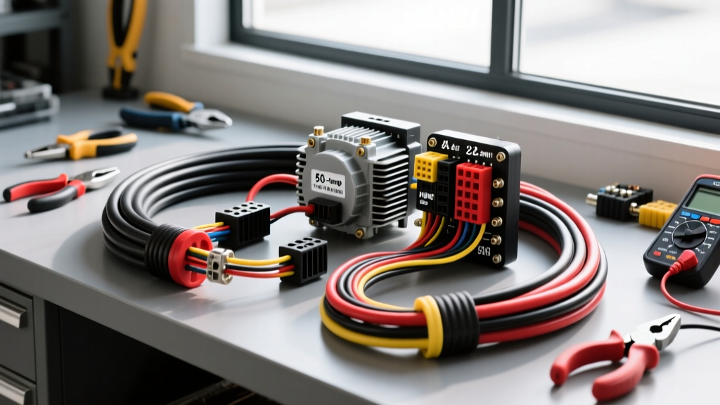
What Gauge Wire for 50 Amp Loads? The SAE J1128 Standard
The 50-amp threshold represents a critical bridge in automotive electrical systems. It separates standard accessory circuits (typically 10A to 30A) from heavy-duty primary power feeds (100A and above). When builders and technicians ask what gauge wire for 50 amp circuits is required, the baseline answer according to the SAE J1128 Standard for Low Tension Automotive Cable is 6 AWG for short, well-ventilated chassis runs, and 4 AWG for extended runs, bundled harnesses, or high-ambient-heat engine bay environments.
Unlike residential wiring governed by the NFPA 70 National Electrical Code (NEC), automotive wiring must account for severe vibration, extreme thermal cycling, and corrosive elements. SAE-compliant wire features a higher strand count than standard building wire of the same AWG, increasing flexibility and surface area for heat dissipation. Selecting the correct gauge is not just about preventing melted insulation; it is about maintaining voltage integrity at the load.
50 Amp Wire Gauge Specification Chart
The following chart details the physical and electrical properties of copper wire typically used for 50A automotive applications. Ampacity ratings are derated for under-hood environments where ambient temperatures routinely exceed 105°C.
| AWG Size | Stranding (SAE) | Nominal O.D. (in) | Resistance @ 20°C (Ω/1k ft) | Max Ampacity (Engine Bay) | Max Ampacity (Cabin/Trunk) |
|---|---|---|---|---|---|
| 8 AWG | 168 | 0.128 | 0.6282 | 35A (Not Rec.) | 45A (Not Rec.) |
| 6 AWG | 259 | 0.162 | 0.3951 | 50A (Standard) | 65A |
| 4 AWG | 413 | 0.204 | 0.2485 | 70A (Heavy Duty) | 85A |
| 2 AWG | 655 | 0.258 | 0.1563 | 95A | 120A |
Real-World Automotive Applications (50A Circuits)
High-Output Alternator Accessory Feeds
When upgrading to a 140A or 200A alternator for off-road lighting or competition audio, the primary charge wire is usually 1/0 AWG or 2 AWG. However, secondary distribution blocks feeding 50A accessories (like electric power steering pumps or air suspension compressors) require dedicated 6 AWG or 4 AWG runs. Using standard Red for the primary 12V+ feed and Black for the high-current chassis ground is mandatory for safety and diagnostic clarity.
EV DC-DC Converters and Inverter Feeds
In electric vehicle conversions and overlanding setups, 50A is a common continuous draw for DC-DC battery chargers (e.g., Victron Orion 12/12-50) or 600W pure sine wave inverters. Because these loads draw a continuous 50A rather than a momentary peak, thermal buildup is a primary concern. A 4 AWG XLPE-insulated wire is heavily recommended to prevent voltage sag and thermal derating inside enclosed battery boxes.
Off-Road Winch Control Circuits
While the main winch power cables (which can see 300A+ peaks) require 2/0 AWG welding cable, the heavy-duty solenoid control circuits and auxiliary 50A accessory relays wired to the winch feed require robust 6 AWG wiring. Orange or Yellow wire is typically used here to denote a switched, high-current 12V+ source.
Insulation Types: GXL vs. SXL vs. PVC
Choosing the correct gauge is only half the battle; the insulation jacket dictates the wire's survivability in harsh automotive environments.
- GXL (Cross-Linked Polyethylene): The industry standard for under-hood wiring. Rated for 125°C, GXL features a thin wall that reduces weight and harness bulk while offering excellent resistance to chemicals, oils, and abrasion.
- SXL (Special Cross-Linked): Rated for 150°C, SXL is required for routing near exhaust manifolds, turbochargers, or EGR systems. It has a slightly thicker wall than GXL for added thermal protection.
- PVC (Polyvinyl Chloride): Standard primary wire rated for 105°C. While acceptable for interior cabin wiring (trunk amplifiers, interior lighting), PVC becomes brittle and melts when exposed to engine bay temperatures. Never use PVC for a 50A under-hood feed.
Termination, Crimping, and Torque Specifications
A 50A circuit will quickly expose poor termination work. High current generates heat, and heat increases resistance, creating a destructive thermal runaway loop.
Crimp Profiles and Tools
For 6 AWG and 4 AWG wire, avoid indent crimpers (which cut into the copper strands and reduce the cross-sectional area). Use a hex-crimp die or a ratcheting hydraulic crimper. Hex crimps compress the copper strands and terminal barrel uniformly, ensuring a gas-tight connection that prevents oxidation.
Heat Shrink and Moisture Sealing
Always use adhesive-lined (dual-wall) heat shrink with a 3:1 shrink ratio. As the heat shrink is applied, the inner meltable adhesive flows into the wire strands, creating a waterproof seal that prevents green copper corrosion (copper oxide), which is highly resistive and a common cause of 50A circuit failures.
Torque Specifications
When securing a 3/8-inch ring terminal to a battery busbar or chassis ground stud, torque matters. Under-torquing leads to arcing and melted lugs. Over-torquing can strip aluminum threads or snap copper studs. For a standard 3/8-inch steel or brass ground stud, torque the nut to 15-20 ft-lbs. Always use a star washer or a dedicated ground plate with serrated teeth to bite through paint and primer, ensuring bare metal-to-metal contact.
Voltage Drop Calculations for 50A Circuits
According to automotive electrical best practices, voltage drop on a 12V accessory circuit should not exceed 3% (0.36V). To determine if 6 AWG is sufficient or if you must step up to 4 AWG, use the standard voltage drop formula:
VD = (2 × L × I × R) / 1000
- L = One-way wire length in feet
- I = Current draw (50A)
- R = Resistance per 1,000 ft (from the chart above)
Scenario A: 8-Foot Run (Engine Bay to Firewall)
Using 6 AWG (R = 0.3951): VD = (2 × 8 × 50 × 0.3951) / 1000 = 0.31V. This is under the 0.36V threshold. 6 AWG is perfectly acceptable.
Scenario B: 15-Foot Run (Battery to Trunk Inverter)
Using 6 AWG: VD = (2 × 15 × 50 × 0.3951) / 1000 = 0.59V (4.9% drop). This will cause inverter low-voltage alarms and excessive wire heating.
Upgrading to 4 AWG (R = 0.2485): VD = (2 × 15 × 50 × 0.2485) / 1000 = 0.37V (3.08% drop). By stepping up to 4 AWG, the circuit operates safely within acceptable parameters. You can verify these calculations dynamically using tools like the Southwire Voltage Drop Calculator.
Troubleshooting Thermal Failure Modes
When diagnosing a failing 50A circuit, look for these specific symptoms:
- Melted Insulation at the Lug: Indicates a poor crimp or insufficient adhesive seal, not necessarily an undersized wire. The resistance at the crimp joint is generating more heat than the wire itself.
- Uniformly Soft/Brittle Wire Jacket: The wire gauge is correct, but the insulation rating is too low (e.g., PVC used in an engine bay). Replace with GXL or SXL.
- Voltage Sag Under Load: If the voltage at the battery reads 13.8V but drops to 11.5V at the 50A load, the wire run is too long for 6 AWG. Upgrade to 4 AWG or 2 AWG to reduce resistance.