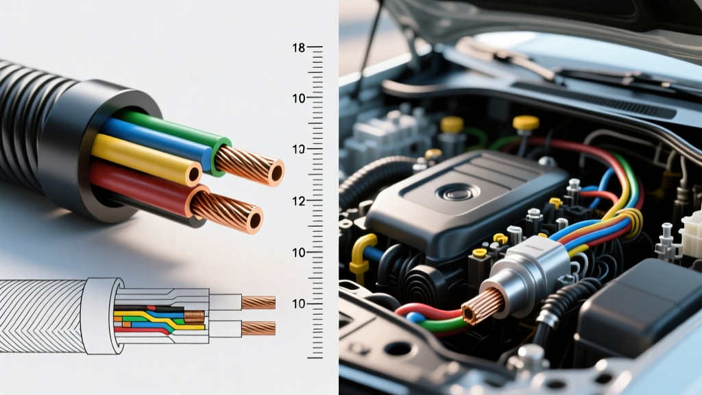
The Core Question: How Many mm is 18 Gauge Wire?
When automotive technicians and engineers ask, "how many mm is 18 gauge wire," the answer requires a critical distinction between linear diameter and cross-sectional area. Confusing these two measurements is one of the most common causes of harness repair failures, leading to terminal push-out, voltage drops, and intermittent sensor codes.
Here are the exact specifications for 18 AWG (American Wire Gauge) copper wire:
- Diameter (mm): 1.024 mm
- Cross-Sectional Area (mm²): 0.823 mm²
- Resistance (Copper @ 20°C): 6.385 Ω per 1,000 feet
- Max Ampacity (Chassis Wiring): ~16 Amps
In the metric system, wire is sized by cross-sectional area (mm²), not diameter. There is no perfect 1:1 metric equivalent to 18 AWG. The closest standard metric sizes are 0.75 mm² (which is slightly thinner, roughly 18.9 AWG) and 1.0 mm² (which is slightly thicker, roughly 17.1 AWG). When repairing an 18 AWG sensor circuit, substituting a 1.0 mm² metric wire can cause the insulation to be too thick for the connector's weather pack seal, leading to moisture intrusion and copper oxide formation (green rot).
Step-by-Step Troubleshooting Flow: 18 AWG Sensor Circuits
18 AWG wire is the backbone of modern automotive low-current signaling. It is the standard size for 5-Volt Reference (5VREF) circuits, MAP/MAF sensor signal returns, oxygen sensor heater controls, and high-speed CAN-Bus networks. When diagnosing a fault code like P0131 (O2 Sensor Circuit Low Voltage) or P0642 (Sensor Reference Voltage A Circuit Low), follow this diagnostic flow to isolate 18 AWG harness faults.
Step 1: Visual Inspection and Terminal Mating (Pin Drag Test)
Before touching a multimeter, verify the physical integrity of the 18 AWG wire at the connector. Most 18 AWG automotive sensors utilize Delphi Metri-Pack 150 or TE Connectivity SuperSeal connectors.
- Disconnect the ECU and Sensor: Ensure the battery negative terminal is disconnected to prevent shorting the 5VREF circuit.
- Inspect the Crimp: Look at the terminal crimp on the 18 AWG wire. The conductor crimp should exhibit a proper 'bellmouth' (a slight flare of wire strands at the front of the crimp barrel). If a previous technician used 1.0 mm² metric wire in an 18 AWG terminal, the insulation crimp will likely be deformed, compromising the silicone weather seal.
- Perform a Pin Drag Test: Insert a known-good male test pin into the female connector cavity. You should feel a distinct mechanical 'click' and slight resistance when withdrawing it. If the pin slides out with zero resistance, the female terminal tangs are fatigued, causing micro-arcing on the 18 AWG signal wire.
Step 2: Voltage Drop Testing on the Signal Wire
A common failure mode in 18 AWG wiring is internal strand corrosion, which increases resistance without visibly damaging the outer PVC or XLPE insulation. Because sensor circuits draw minimal current (often less than 50mA), a standard continuity test will falsely show a 'good' wire. You must perform a dynamic voltage drop test.
- Reconnect the ECU and Sensor: Back-probe the 18 AWG signal wire at the sensor connector using a fine T-pin or dedicated back-probe tool. Do not pierce the wire insulation, as this creates a capillary path for moisture.
- Set Multimeter to DC Volts: Place the positive lead on the back-probed sensor pin and the negative lead directly on the ECU connector pin for that same circuit (e.g., Pin 42 on a GM E38 ECM for the MAP signal).
- Key On, Engine Off (KOEO): Read the voltage. For a 5VREF circuit, the maximum allowable voltage drop across the 18 AWG wire is 0.1V. If your multimeter reads a 0.3V drop, the 18 AWG wire has excessive internal resistance and must be replaced or bypassed.
Step 3: Oscilloscope Analysis for High-Frequency 18 AWG Circuits
When 18 AWG wire is used for CAN-Bus (Controller Area Network), resistance and capacitance dictate signal integrity. A break in the 18 AWG twisted pair will cause signal reflection and module dropout.
- Connect the Scope: Channel A to CAN-High, Channel B to CAN-Low.
- Verify Differential Voltage: CAN-H should peak at ~3.5V and CAN-L should drop to ~1.5V. The sum should always equal 5V.
- Check for Impedance Mismatch: If the waveform shows 'ringing' (jagged edges on the square waves), a previous repair likely spliced a 1.0 mm² or 1.5 mm² metric wire into the 18 AWG CAN harness. The change in cross-sectional area alters the characteristic impedance of the twisted pair, causing data corruption and U-codes (e.g., U0100 Lost Communication with ECM).
Technical Reference Chart: AWG vs. Metric Wire Sizing
Use this reference table when ordering replacement wire or selecting crimp dies for automotive harness repairs. Always match the cross-sectional area (mm²) rather than the linear diameter (mm) to ensure proper terminal crimping.
| AWG Size | Diameter (mm) | Cross-Section (mm²) | Nearest Metric Equivalent | Typical Automotive Application |
|---|---|---|---|---|
| 20 AWG | 0.812 mm | 0.518 mm² | 0.50 mm² | Airbag clock springs, steering wheel controls |
| 18 AWG | 1.024 mm | 0.823 mm² | 0.75 mm² / 1.0 mm² | O2 Sensors, MAP/MAF, CAN-Bus, 5VREF |
| 16 AWG | 1.291 mm | 1.309 mm² | 1.50 mm² | Headlight grounds, injector power feeds |
| 14 AWG | 1.628 mm | 2.082 mm² | 2.00 mm² | Accessory power, blower motor relays |
| 12 AWG | 2.053 mm | 3.309 mm² | 3.00 mm² | Fuel pump feeds, high-amperage grounds |
Real-World Case Study: Ford HS-CAN Communication Fault
Vehicle: 2018 Ford F-150 3.5L EcoBoost
Symptom: Intermittent U0100 (Lost Communication with PCM) and erratic shift points.
Diagnosis: The High-Speed CAN network utilizes an 18 AWG twisted pair. At the OBD2 Data Link Connector (DLC), CAN-High is Pin 14 (typically White/Blue) and CAN-Low is Pin 15 (typically White/Brown).
Using a digital storage oscilloscope (DSO), we observed severe signal reflection on the CAN-High circuit. A visual inspection behind the passenger kick panel revealed a previous aftermarket alarm installation where the installer had spliced into the 18 AWG CAN wires using 16 AWG (1.31 mm²) wire. The larger gauge wire altered the twisting ratio and impedance of the bus. Furthermore, the solder joint was wrapped in standard vinyl electrical tape, which unraveled due to under-dash heat cycles, allowing the shielded drain wire to intermittently short against the 18 AWG signal wire.
Resolution: We removed the incorrect 16 AWG splice, repaired the 18 AWG harness using OEM-spec Ford Motorcraft 18 AWG cross-linked polyethylene (XLPE) wire, and utilized a ratcheting open-barrel crimper with heat-shrink adhesive seals to restore the factory 120-ohm termination and twisted-pair geometry.
Authoritative References & Standards
For further technical data on wire gauge specifications, crimping standards, and automotive electrical diagnostics, consult the following authoritative resources:
- SAE J1128: Low Tension Primary Cable Standard - The Society of Automotive Engineers' definitive guide on insulation types, temperature ratings, and AWG sizing for automotive primary wire.
- Copper Development Association (CDA) - The global authority on copper wire properties, including exact AWG to mm resistance and ampacity charts.
- Madsen Wire AWG to Metric Conversion Chart - A highly trusted industry reference for translating American Wire Gauge to metric cross-sectional areas for harness manufacturing.