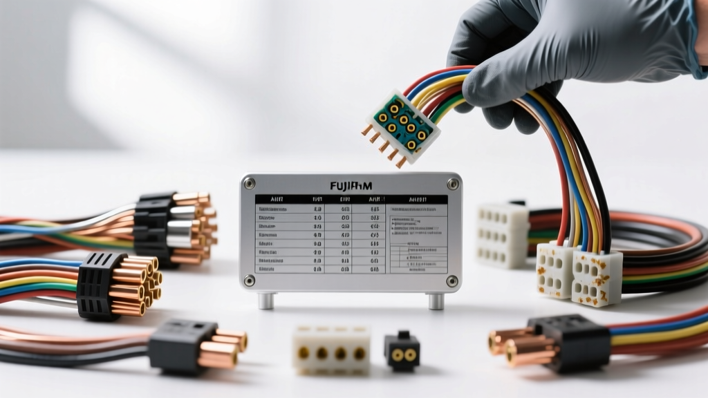
The Hidden Dangers of Aluminum and CCA Wiring in Automotive Systems
While Oxygen-Free Copper (OFC) remains the gold standard for automotive electrical systems, weight-saving initiatives in EV platforms and cost-cutting measures in aftermarket accessories have introduced aluminum and Copper-Clad Aluminum (CCA) wires into the 12V and 48V automotive ecosystem. When an undersized aluminum cable is used for high-amperage draws—such as a 150A alternator upgrade, an electric winch, or a high-output inverter—the result is severe voltage drop, thermal runaway, and catastrophic connector failure.
Because aluminum has approximately 61% the conductivity of copper, a direct 1:1 AWG substitution will inevitably lead to system starvation. This step-by-step troubleshooting flow utilizes an aluminum wire gauge table to help automotive technicians and DIYers accurately diagnose voltage drops, identify galvanic corrosion, and rectify high-resistance faults in mixed-metal circuits.
Step 1: Identify the Wire Material (The Scratch and Weight Tests)
Before consulting any reference charts, you must confirm the conductor material. Many aftermarket power wire kits marketed for car audio or auxiliary lighting use CCA (Copper-Clad Aluminum) disguised as pure copper.
- The Scratch Test: Use a utility knife to scrape the surface of the wire strand. If the bright copper color gives way to a dull silver or white core, you are dealing with CCA or pure aluminum.
- The Weight Test: Aluminum is roughly 70% lighter than copper. If a spool of 4 AWG wire feels suspiciously light, it is likely aluminum-based.
- The Oxidation Check: Inspect the cut ends of the wire. Pure copper oxidizes to a dark brown or green. Aluminum oxidizes to a chalky white powder (aluminum oxide), which is highly resistive and acts as an electrical insulator.
Step 2: Consult the Aluminum Wire Gauge Table & Ampacity Chart
Once aluminum or CCA is confirmed, you must re-evaluate the circuit's ampacity. According to baseline conductivity standards referenced in the NFPA National Electrical Code (NEC) Chapter 9, aluminum requires a cross-sectional area roughly 1.5 times larger than copper to carry the same current safely without exceeding thermal limits.
Use the aluminum wire gauge table below to cross-reference your physical wire size against its true automotive ampacity and resistance profile.
| AWG Size | Copper (OFC) Ampacity (Chassis) | Aluminum / CCA Ampacity (Chassis) | Copper Resistance (Ohms/1000ft) | Aluminum Resistance (Ohms/1000ft) |
|---|---|---|---|---|
| 8 AWG | 40A - 50A | 25A - 30A | 0.6282 | 1.0000 |
| 4 AWG | 60A - 80A | 45A - 55A | 0.2485 | 0.3951 |
| 2 AWG | 95A - 120A | 75A - 90A | 0.1563 | 0.2485 |
| 1/0 AWG | 150A - 190A | 120A - 145A | 0.0983 | 0.1563 |
| 4/0 AWG | 260A - 320A | 205A - 250A | 0.0490 | 0.0778 |
Note: Automotive 'chassis wiring' ampacity assumes short runs (under 15 feet) and single conductors in free air. Bundled wires in engine bays require further derating due to ambient heat.
Step 3: Perform the Voltage Drop Test (Troubleshooting Flow)
If your aluminum wire gauge table indicates the wire is undersized for the load, or if you suspect a high-resistance joint, perform a dynamic voltage drop test. Never measure resistance with an ohmmeter on a live circuit; instead, measure the voltage drop under load.
- Setup: Set your digital multimeter (DMM) to DC Volts (20V range).
- Positive Side Test: Place the red probe directly on the battery positive post (not the clamp) and the black probe on the component's positive input terminal (e.g., the winch motor stud or inverter busbar).
- Apply Load: Activate the component. For a winch, apply a load using a synthetic strap and a static object. For an alternator, turn on all high-draw accessories (headlights, rear defroster, blower motor on high) and rev to 2000 RPM.
- Negative Side Test: Move the red probe to the component's negative terminal and the black probe to the battery negative post. Record the reading.
Decision Tree: Interpreting Voltage Drop Readings
- Reading < 0.10V per connection / < 0.30V total circuit: Circuit is healthy. The aluminum/CCA gauge is sufficient for the load.
- Reading 0.30V to 0.50V total: Marginal voltage drop. The wire may be correctly sized but is suffering from thermal resistance or minor terminal oxidation. Proceed to Step 4.
- Reading > 0.50V total: Severe voltage drop. The aluminum wire is undersized for the amperage, or a major galvanic corrosion block exists at a crimp joint. Immediate remediation required.
Step 4: Inspect for Galvanic Corrosion and Cold Flow
When troubleshooting aluminum automotive wiring, the wire itself is rarely the sole culprit; the termination points are where 90% of failures occur. Aluminum exhibits two unique physical properties that destroy standard copper crimps and ring terminals.
1. Galvanic Corrosion at Bimetallic Junctions
When aluminum wire is crimped into a standard copper or tinned-copper ring terminal, moisture and road salt act as an electrolyte. This creates a galvanic cell where the aluminum (the anode) sacrifices itself to the copper (the cathode). The resulting aluminum oxide builds up inside the crimp barrel, exponentially increasing resistance. If you disconnect an ANL fuse holder or a battery isolation stud and see a white, crusty powder, galvanic corrosion has compromised the circuit.
2. Thermal Creep (Cold Flow)
Aluminum expands and contracts at a different rate than copper or steel under thermal cycling. Furthermore, aluminum exhibits 'creep'—it slowly deforms under constant mechanical pressure. A standard hex-crimp that was perfectly tight on day one will become loose after 50 heat cycles in an engine bay. This loose connection causes micro-arcing, melting the terminal insulation and creating a fire hazard. As noted in SAE J1128 surface vehicle wiring standards, maintaining terminal clamping force is critical for low-tension primary and heavy-gauge secondary cables.
Step 5: Remediation and Upgrading to OFC
If your troubleshooting confirms that the aluminum wire gauge table limits have been exceeded, or if terminal corrosion is unmanageable, you must remediate the circuit.
- Upgrade to OFC: The most reliable fix is replacing the CCA/Aluminum run with pure Oxygen-Free Copper (OFC). If replacing a 2 AWG aluminum cable, use a 2 AWG or 4 AWG OFC cable to restore proper ampacity and reduce voltage drop.
- Use Bimetallic Lugs: If you must retain the aluminum cable (common in heavy-duty EV battery interconnects or commercial trucking), you must use specialized aluminum-to-copper bimetallic lugs. These feature an aluminum barrel for the wire and a copper pad for the busbar, preventing galvanic interaction.
- Apply Anti-Oxidant Compound: Never crimp or bolt bare aluminum wire without applying a conductive anti-oxidant paste like Noalox or Penetrox-A. These compounds contain zinc dust or copper particles suspended in grease, which breaks through the aluminum oxide layer during crimping and seals out moisture.
- Never Solder Aluminum: Do not attempt to tin or solder aluminum or CCA wire with standard rosin-core solder. The solder will not bond properly to the aluminum core, and the rigid solder joint will snap under chassis vibration. Always use high-tonnage hex crimps.
Authoritative References
For further reading on automotive wiring standards, conductivity baselines, and terminal crimp specifications, consult the following resources: