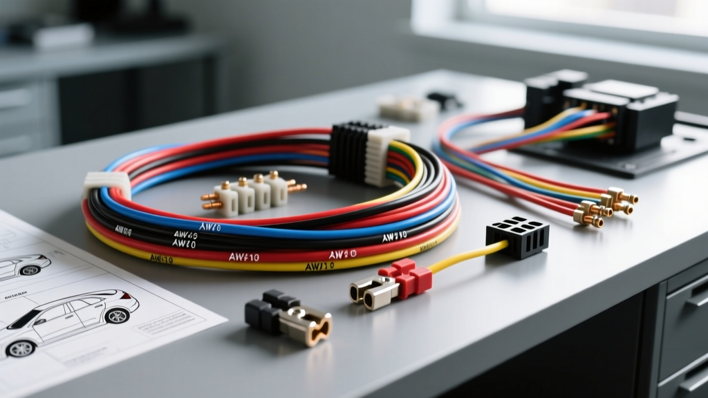
The Role of an AWG Wire Gauge Chart PDF in Automotive Diagnostics
When diagnosing complex automotive electrical failures—ranging from flickering headlights to melted fuel pump harnesses—technicians cannot rely on guesswork. A fundamental step in verifying circuit integrity is cross-referencing the physical wire against an AWG wire gauge chart PDF to ensure the installed cabling matches the circuit’s ampacity and voltage drop requirements. North American manufacturers predominantly use the American Wire Gauge (AWG) system, while metric platforms rely on cross-sectional area (mm²). Having a comprehensive AWG wire gauge chart PDF on hand bridges this gap, allowing you to verify copper stranding, diameter, and resistance per foot against SAE J1128 Standard for Low Tension Primary Cable specifications.
This guide outlines a rigorous, step-by-step troubleshooting flow for diagnosing undersized, degraded, or improperly repaired automotive wiring. By following this sequence, you will isolate voltage drops, verify terminal crimps, and execute permanent corrections based on hard engineering data.
Step 1: Symptom Verification and Voltage Drop Testing
Before cutting into any harness or pulling out an AWG wire gauge chart PDF, you must quantify the electrical fault. The most common symptom of an undersized or degraded wire is excessive voltage drop under load, which manifests as dim lighting, slow power window operation, or fuel pump whining.
Performing a Dynamic Voltage Drop Test
- Set up the Multimeter: Set your digital multimeter (DMM) to the DC millivolt (mV) scale.
- Activate the Circuit: The circuit must be under load and actively flowing current. A static continuity test will not reveal high-resistance faults.
- Probe the Connections: Place the red probe on the battery positive terminal and the black probe on the load side of the fuse or connector. For ground circuits, place the red probe on the load’s ground pin and the black probe directly on the battery negative post.
- Evaluate the Readings: According to standard automotive diagnostic parameters, a maximum acceptable voltage drop is 0.2V (200mV) for ground circuits and 0.5V (500mV) for 12V positive feed circuits. If your reading exceeds these thresholds, high resistance exists in the wire or terminal.
If the voltage drop is localized to a specific length of wire rather than a connector, the wire itself is likely undersized for the current draw, internally corroded, or suffering from broken copper strands inside the insulation.
Step 2: Wire Extraction and Physical Measurement
Once the fault is isolated to a specific wire run, you must verify its gauge. Visual estimation is notoriously inaccurate, especially with modern thin-wall insulation types like GXL or TXL, which have a smaller outer diameter than older TWG wire but carry the same current.
- Strip the Insulation: Carefully strip back 1/2 inch of the primary insulation without nicking the copper strands.
- Measure the Conductor: Use a digital micrometer to measure the bare copper diameter. For stranded wire, compress the strands gently with the micrometer anvil to get an accurate reading of the copper cross-section, excluding air gaps.
- Consult the Chart: Reference your AWG wire gauge chart PDF to match the micrometer reading to the correct AWG size and verify its cross-sectional area in square millimeters (mm²).
Reference Table: Automotive AWG to Millimeter & Ampacity Chart
The following data is derived from standard chassis wiring guidelines and NFPA 70 (National Electrical Code) Article 310 ampacity baselines, adjusted for the high-temperature, bundled-harness environment of a vehicle engine bay.
| AWG Size | Diameter (mm) | Cross-Section (mm²) | Max Amps (Chassis)* | Ohms per 1,000 ft (Copper) |
|---|---|---|---|---|
| 18 AWG | 1.02 | 0.82 | 6A - 8A | 6.385 |
| 16 AWG | 1.29 | 1.31 | 10A - 12A | 4.016 |
| 14 AWG | 1.63 | 2.08 | 15A - 18A | 2.525 |
| 12 AWG | 2.05 | 3.31 | 20A - 25A | 1.588 |
| 10 AWG | 2.59 | 5.26 | 30A - 40A | 0.999 |
| 8 AWG | 3.26 | 8.37 | 50A - 60A | 0.628 |
*Note: Max amperage varies based on wire length, ambient temperature, and whether the wire is bundled in a loom. Always apply a 20% derating factor for wires routed through engine bays exceeding 105°C.
Step 3: Connector and Terminal Cross-Referencing
A wire is only as good as its termination. After confirming the wire gauge via your AWG wire gauge chart PDF, you must verify that the terminal crimp matches the wire size. Using a 14 AWG terminal on a 16 AWG wire results in a loose mechanical connection that will arc, oxidize, and eventually melt the connector housing.
For modern GM, Ford, and Chrysler applications, Aptiv (Delphi) Metri-Pack Connection Systems are the industry standard. These open-barrel (F-crimp) terminals require precise crimping tools. If you are repairing a circuit, ensure your replacement terminal matches both the wire gauge and the connector cavity size (e.g., Metri-Pack 150 series for 18-22 AWG, Metri-Pack 280 series for 12-16 AWG, and Metri-Pack 630 series for 8-10 AWG).
Step 4: Real-World Case Study: GMT800 Fuel Pump Voltage Drop
To illustrate this troubleshooting flow, consider the notorious fuel pump wiring issue found in 1999-2006 GM GMT800 platforms (Silverado, Sierra, Tahoe). Owners frequently report hard starting, hesitation, or premature fuel pump failure.
The Diagnostic Flow
- Symptom: Fuel pump whine and low fuel pressure (below 55 PSI) under load.
- Voltage Drop Test: Back-probing the 4-pin Delphi Weather-Pack connector at the fuel tank sender. Pin A (Gray, 12V Feed) shows a 1.2V drop from the battery positive. Pin B (Black, Ground) shows a 0.6V drop to battery negative. Both exceed acceptable limits.
- Wire Verification: Stripping back the Gray and Black wires reveals they are 16 AWG (approx. 1.31 mm²).
- The Engineering Flaw: High-pressure EFI fuel pumps draw between 12A and 15A continuously. According to our AWG wire gauge chart PDF, 16 AWG wire is rated for a maximum of 10A-12A in a bundled, high-heat environment. The factory undersized the main feed and ground wires, causing them to act as resistors. This voltage drop starves the pump of amperage, causing it to overwork, overheat, and fail prematurely.
Step 5: Corrective Repair and Sealing
Once the AWG wire gauge chart PDF confirms the factory wire is inadequate, the corrective action is to upgrade the circuit. For the GMT800 fuel pump, the fix involves bypassing the factory 16 AWG Gray and Black wires with 12 AWG primary wire.
Execution Steps
- Splicing: Use adhesive-lined, dual-wall heat shrink butt connectors. Solder the connection before crimping to ensure maximum conductivity and vibration resistance.
- Terminal Replacement: Cut off the factory Weather-Pack pins. Strip the new 12 AWG wire and crimp on new 12 AWG Weather-Pack terminals using a ratcheting open-barrel crimper. The insulation grip must secure the wire jacket, while the conductor grip secures the bare copper.
- Ground Stud Torque: When reattaching the upgraded 12 AWG Black ground wire to the chassis, clean the metal surface down to bare steel using a wire wheel. Use a star washer to bite through any surface oxidation. Torque the ground stud to 10 Nm (89 lb-in) to ensure a permanent, low-resistance path.
- Loom Protection: Wrap the upgraded 12 AWG wires in split-loom tubing and secure it with Tesa 51036 high-temperature harness tape to prevent chafing against the fuel tank straps.
Conclusion
Automotive electrical troubleshooting requires moving beyond simple fuse checks and continuity tests. By integrating a dynamic voltage drop test with physical measurements verified against an AWG wire gauge chart PDF, you can accurately diagnose factory engineering flaws, previous botched repairs, and degraded harnesses. Whether you are upgrading a fuel pump feed, wiring a high-draw off-road light bar, or diagnosing a melted alternator charge cable, respecting the physics of wire gauge, ampacity, and terminal crimp geometry is the hallmark of a master technician.