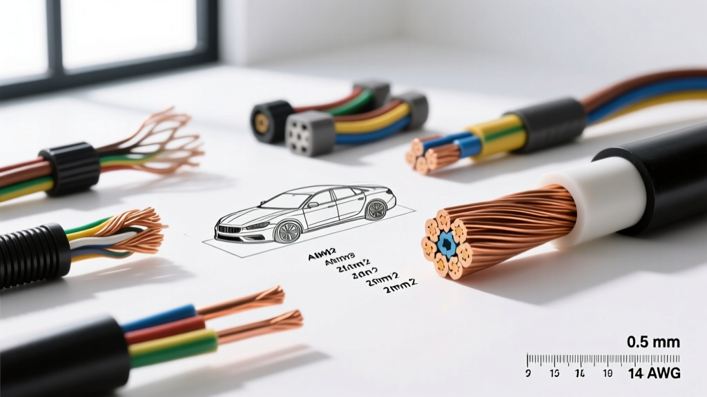
The Physics of Wire Gauge Diameter: Area vs. Outer Dimension
When automotive technicians and electrical engineers discuss wire gauge diameter, they are often conflating two entirely different physical measurements: the conductor diameter and the overall outer diameter (OD) including insulation. The American Wire Gauge (AWG) system is not a direct linear measurement; it is a logarithmic step function based on the cross-sectional area of the conductor. The formula for the diameter of a solid AWG wire is d = 0.005 × 92^((36-AWG)/39) inches. However, in automotive applications, solid core wire is almost never used due to the severe vibration and flexing inherent in vehicle chassis and engine bays.
Understanding the exact wire gauge diameter is critical for selecting the correct terminal housings, grommets, and crimp dies. A miscalculation in the outer diameter can lead to compromised environmental seals in Weatherpack or Metri-Pack connectors, resulting in moisture ingress, galvanic corrosion, and eventual circuit failure.
The Stranding Factor: Why SAE J1128 Differs from Solid Core
Automotive primary cable is governed by the SAE J1128 standard, which dictates the requirements for low-tension, stranded copper wire. Because stranded wire consists of multiple smaller copper filaments twisted together, interstitial air gaps exist between the strands. Consequently, a stranded 12 AWG wire will have a larger physical conductor diameter than a solid 12 AWG wire, even though their cross-sectional copper area (and therefore their DC resistance) remains virtually identical.
Furthermore, the insulation material radically alters the final wire gauge diameter. Modern automotive wiring relies heavily on Cross-Linked Polyethylene (XLPE) insulation, classified as GXL (125°C rating) or SXL (150°C rating). XLPE offers superior thermal and abrasion resistance compared to traditional Polyvinyl Chloride (PVC) insulation (classified as TWP). Because XLPE is mechanically stronger, manufacturers can extrude it in much thinner walls. For example, a 14 AWG TWP wire might have an OD of 2.80 mm, while a 14 AWG SXL wire achieves an OD of just 2.35 mm, allowing for tighter routing in dense engine harnesses.
Master Automotive Wire Gauge Diameter & Resistance Chart
The following reference table bridges the gap between AWG sizes, metric cross-sectional equivalents, and the physical dimensions required for harness design. All resistance values are calculated for annealed copper at 20°C (68°F).
| AWG Size | Metric Equiv. (mm²) | Stranded Conductor Dia. (mm) | SAE J1128 (SXL) Insulation Wall (mm) | Total Outer Diameter (OD) (mm) | DC Resistance @ 20°C (mΩ/m) |
|---|---|---|---|---|---|
| 18 AWG | 0.80 | 1.02 | 0.28 | 1.58 | 21.40 |
| 16 AWG | 1.30 | 1.29 | 0.28 | 1.85 | 13.20 |
| 14 AWG | 2.00 | 1.63 | 0.36 | 2.35 | 8.28 |
| 12 AWG | 3.00 | 2.05 | 0.36 | 2.77 | 5.21 |
| 10 AWG | 5.00 | 2.59 | 0.46 | 3.51 | 3.28 |
| 8 AWG | 8.00 | 3.26 | 0.56 | 4.38 | 2.06 |
| 6 AWG | 13.0 | 4.11 | 0.66 | 5.43 | 1.30 |
| 4 AWG | 19.0 | 5.19 | 0.76 | 6.71 | 0.815 |
| 2 AWG | 32.0 | 6.54 | 0.91 | 8.36 | 0.513 |
| 1/0 AWG | 50.0 | 8.25 | 1.12 | 10.49 | 0.322 |
Note: Metric equivalents are nominal automotive industry standards (ISO 6722) and do not represent exact mathematical conversions of circular mils to square millimeters.
High-Amperage Applications: Managing Voltage Drop and Terminal Crimps
When routing high-current circuits—such as alternator charge wires, starter solenoid feeds, or electric power steering (EPS) supplies—the wire gauge diameter directly dictates the terminal hardware. A common failure mode in aftermarket high-output alternator upgrades (e.g., upgrading from a 100A to a 220A unit) is the reuse of factory 10 AWG or 8 AWG wiring. This results in severe voltage drop, causing the ECU to log charging system faults and dimming headlights under load.
Case Study: LS-Engine Swap Battery Relocation (1/0 AWG)
In performance applications like an LS-engine swap with a trunk-mounted battery, technicians typically utilize 1/0 AWG welding cable or SAE J1128 SGX battery cable. The stranded conductor diameter of 1/0 AWG is approximately 8.25 mm, but the highly flexible welding cable variant can swell to 9.5 mm due to a higher strand count and thinner EPDM insulation.
Execution Protocol:
- Terminal Selection: Use heavy-duty, closed-barrel ring terminals (e.g., Molex Perma-Seal or TE Connectivity PIDG) rated for 1/0 AWG with a 3/8-inch stud hole to fit standard battery isolation studs and starter B+ posts.
- Crimping Mechanics: Do not use hex-crimp pliers. A hydraulic crimper with a dedicated 1/0 AWG hex die (typically 50mm²) is mandatory to achieve the required 4,000+ lbs of crimp force. This ensures the copper strands cold-flow into a solid mass, eliminating internal air pockets that cause localized resistance heating.
- Environmental Sealing: Slide dual-wall, adhesive-lined heat shrink (minimum 3:1 shrink ratio, 12mm pre-shrink diameter) over the wire before crimping. Apply heat at 120°C until the inner thermoplastic adhesive extrudes slightly from the edges, creating a waterproof barrier against under-carriage salt and moisture.
High-Frequency Networks: CAN Bus Impedance and Wire Diameter
While DC power circuits rely purely on cross-sectional area to minimize voltage drop, high-speed data networks like Controller Area Network (CAN) bus are highly sensitive to the physical wire gauge diameter and insulation geometry. Modern vehicles utilize ISO 11898-2 compliant High-Speed CAN, operating at up to 1 Mbps.
CAN bus requires an Unshielded Twisted Pair (UTP) with a strict characteristic impedance of 120 ohms. This impedance is a function of the conductor diameter, the dielectric constant of the insulation, and the distance between the two conductors. The Texas Instruments CAN Physical Layer Design Guide explicitly notes that deviations in wire geometry will cause signal reflections.
Automotive manufacturers typically specify 0.35 mm² (approx. 22 AWG) or 0.50 mm² (approx. 20 AWG) conductors for CAN-H and CAN-L circuits. The wire colors are universally standardized across most OEMs: CAN-High is typically Yellow or White with a Green tracer, and CAN-Low is Yellow or White with a Brown tracer. The twist rate is strictly maintained at roughly 1 twist per 25mm (1 inch). If a technician repairs a broken CAN wire using standard 18 AWG primary wire, the increased conductor diameter and altered dielectric spacing will drop the local impedance, causing signal reflection, corrupted data frames, and a cascade of U-codes (communication network faults) across multiple modules.
Metallurgy and Conductivity: OFHC vs. ETP Copper
The final variable influencing the performance of a specific wire gauge diameter is the copper metallurgy. Standard automotive wire utilizes Electrolytic Tough Pitch (ETP) copper (C11000), which is 99.9% pure. However, in high-end motorsport and aerospace applications, Oxygen-Free High Conductivity (OFHC) copper (C10100) is preferred. While the physical wire gauge diameter remains identical, OFHC copper eliminates copper oxide inclusions, offering marginally better conductivity and vastly superior resistance to embrittlement when exposed to high-temperature engine bay environments over prolonged periods.
Authoritative Standards and References
For engineers and master technicians designing custom harnesses or diagnosing complex voltage drop issues, adhering to established industry standards is non-negotiable. The following resources provide the foundational mathematics and material science for automotive wire gauge specifications:
- SAE International: The SAE J1128 standard remains the definitive guide for low-tension primary cable physical dimensions, insulation thermal ratings, and abrasion resistance testing in North American automotive markets.
- Copper Development Association (CDA): The CDA provides exhaustive data tables on the electrical conductivity, thermal expansion, and tensile strength of various copper alloys used in stranded wire manufacturing.
- ISO Standards: For global and European vehicle platforms, ISO 6722 (Road vehicles — 60 V and 600 V single-core cables) dictates the metric cross-sectional requirements and thin-wall insulation tolerances that supersede AWG measurements.