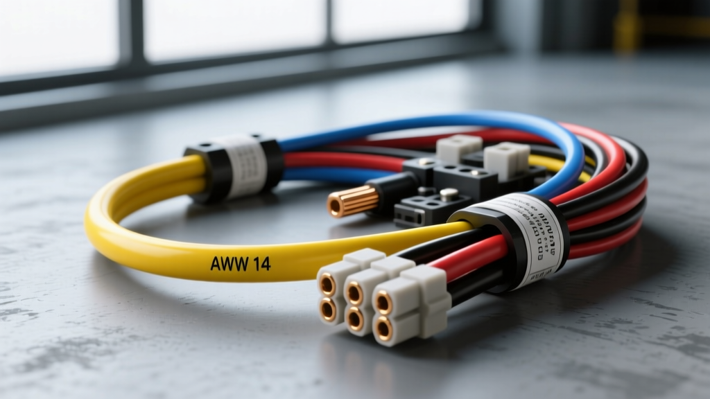
The Core Misconception: Color vs. AWG in Automotive Wiring
When DIYers and junior technicians ask, "what gauge is yellow wire?", they are usually applying residential electrical logic to automotive systems. In standard household NM-B (Romex) wiring, a yellow outer sheath strictly dictates a 12 AWG copper conductor rated for 20 amps. However, in automotive and heavy-duty mobile applications governed by SAE J1128 standards, wire color never dictates the American Wire Gauge (AWG).
In a vehicle, wire color indicates circuit function, not current-carrying capacity. A yellow wire in an engine bay could be a massive 8 AWG starter solenoid feed, or it could be a delicate 22 AWG Controller Area Network (CAN) data line. Assuming a gauge based on color in an automotive environment is a critical diagnostic error that can lead to blown fuses, melted harnesses, or accidental airbag deployment. To properly troubleshoot a yellow wire, you must first physically verify its gauge, then use a functional decision tree to isolate the circuit.
Automotive Yellow Wire Functional Matrix
Before testing, cross-reference the yellow wire's physical thickness and location against this functional matrix to determine its likely purpose and safe testing parameters.
| Circuit Function | Typical AWG | Insulation Type | Common Applications & Locations |
|---|---|---|---|
| SRS / Airbag | 18-20 AWG | Yellow/Red or Yellow/Green Stripe | Clock springs, seat pretensioners, impact sensors (often with yellow connectors) |
| CAN Bus (HS/LS) | 20-22 AWG | Cross-linked (TXL/GXL) | OBD-II DLC (Pins 6 & 14), ECU networks, ABS module data lines |
| Starter / Ignition Feed | 8-12 AWG | SXL / Heavy PVC | Starter solenoids, ignition switch outputs, heavy relay feeds |
| Audio / Memory Constant | 14-16 AWG | Standard PVC | Aftermarket head unit harnesses (DIN), constant 12V memory feeds |
Step-by-Step Yellow Wire Troubleshooting Flow
Follow this systematic diagnostic flow to safely identify, test, and repair yellow automotive wiring. Never skip the visual gauge verification step.
Phase 1: Visual Inspection and Gauge Verification
Because automotive wire uses multi-strand copper, visual estimation is notoriously inaccurate, especially when accounting for different insulation thicknesses. According to AutoShop101 Automotive Electrical Training, modern vehicles use TXL (thin-wall) or GXL (general-purpose thin-wall) cross-linked polyethylene insulation. A 16 AWG TXL wire has the same outer diameter as a 14 AWG standard PVC wire, fooling the naked eye.
- Non-Destructive Method: Use digital calipers to measure the outer diameter (OD) of the wire, then consult an SAE J1128 OD chart. Alternatively, use a dedicated wire gauge wheel tool with notches designed for stranded automotive wire.
- Destructive Method: Strip 1/2 inch of insulation from a redundant section or pigtail. Use a standard AWG stripping gauge or measure the bare copper bundle diameter (e.g., 18 AWG stranded copper is approximately 1.02mm; 12 AWG is approximately 2.05mm).
Phase 2: Circuit Function Isolation (The Decision Tree)
Once the physical gauge is confirmed, route your troubleshooting through the appropriate scenario below.
Scenario A: The Yellow Wire is 18-20 AWG (Signal / SRS)
Symptom: Airbag warning lamp illuminated, or diagnostic trouble codes (DTCs) indicating high/low resistance in the restraint system. Location: Under seats, steering column, B-pillars. CRITICAL WARNING: Never backprobe a yellow SRS wire with standard multimeter probes. Piercing the insulation can cause a short, and the multimeter's internal test current (often 1-10mA) is enough to trigger an explosive squib. Furthermore, NHTSA Airbag and SRS Safety Guidelines mandate that the vehicle battery must be disconnected and the system allowed to discharge for at least 15 minutes before any physical harness manipulation.
- Action 1: Inspect the yellow connector (SRS connectors are universally colored yellow). Look for terminal fretting or 'green death' (copper oxide corrosion).
- Action 2: Do not measure resistance directly through the airbag module. Instead, use an OEM-specific SRS simulator pigtail to isolate the fault to either the wiring harness or the module itself.
- Action 3: If a break is found, SRS circuits generally prohibit standard soldering due to the risk of creating a high-resistance joint that the SRS module will flag as a fault. Use OEM-specified ultrasonic welding or approved open-barrel crimps.
Scenario B: The Yellow Wire is 20-22 AWG (CAN Bus Network)
Symptom: U-codes (Network communication faults), OBD-II scanner fails to link, or multiple modules dropping offline. Location: OBD-II Data Link Connector (DLC), ECU harnesses. Context: On the standard OBD-II DLC, Pin 6 (CAN-High) and Pin 14 (CAN-Low) frequently utilize yellow/green or yellow/brown twisted pairs.
- Action 1 (Resistance Test): With the battery disconnected, measure resistance between CAN-H and CAN-L at the DLC. You should read exactly 60 ohms (two 120-ohm terminating resistors in parallel). If you read 120 ohms, one terminating resistor or a yellow wire branch is open. If you read near 0 ohms, the yellow wires are shorted together.
- Action 2 (Oscilloscope Test): A standard multimeter cannot read CAN bus differential signaling accurately. Connect an oscilloscope. CAN-H should idle at 2.5V and spike to 3.5V; CAN-L should idle at 2.5V and drop to 1.5V. If the yellow wire signal is flatlined, trace the harness for a chafed ground or broken twisted pair.
- Action 3 (Repair): When repairing yellow CAN bus wires, you must maintain the twisted pair geometry. A minimum of 1 twist per inch (approx. 25mm) is required to reject common-mode electromagnetic interference (EMI). Untwisting the yellow wires for more than 2 inches will cause high-speed data packet loss.
Scenario C: The Yellow Wire is 8-12 AWG (High-Current Power)
Symptom: Slow cranking, dimming lights, or a melted fuse block terminal. Location: Starter solenoid, ignition switch, high-amperage relay boxes.
- Action 1 (Voltage Drop Test): Set your Digital Multimeter (DMM) to the DC Millivolt (mV) scale. Connect the red probe to the battery positive post and the black probe to the terminal at the end of the yellow wire. Have an assistant crank the engine or load the circuit.
- Action 2 (Evaluate): A healthy 8-12 AWG power circuit should exhibit a voltage drop of less than 200mV (0.2V) under load. If your DMM reads 400mV or higher, the yellow wire has internal strand corrosion, a failing crimp terminal, or is undersized for the aftermarket load (e.g., an aftermarket audio amplifier drawing 60A through a factory 12 AWG yellow memory wire).
- Action 3 (Thermal Inspection): Use an infrared thermometer to scan the length of the yellow wire under load. A localized hot spot indicates a high-resistance internal break where the remaining copper strands are overloading.
Phase 3: Repair Protocols by Gauge and Function
Once the fault in the yellow wire is isolated, the repair method must match the wire gauge and circuit criticality.
- For 18-22 AWG (Signal/CAN): Use TE Automotive or Molex MX150 open-barrel crimps. Strip exactly 3mm of insulation. Crimp the wire barrel, then the insulation grip. Seal with dual-wall, adhesive-lined heat shrink to prevent moisture ingress, which causes galvanic corrosion in low-voltage signal wires.
- For 8-12 AWG (Power/Starter): Use closed-barrel, heavy-duty copper terminals. While soldering is acceptable for thick gauge power wires, it must always be paired with a mechanical strain-relief crimp. Solder alone will fatigue and crack under the high-frequency vibration of an engine bay, leading to an intermittent open circuit. Always seal the termination with 3:1 shrink ratio adhesive heat shrink to block road salt and moisture.
Summary: Gauge Dictates the Test, Color Dictates the System
To answer the question "what gauge is yellow wire" in an automotive context: it is whatever gauge the engineer selected for that specific circuit's current and voltage requirements. By abandoning residential color-code assumptions and relying on physical AWG measurement, functional matrix cross-referencing, and circuit-specific testing protocols, you can safely and accurately diagnose any yellow wire in a modern vehicle.