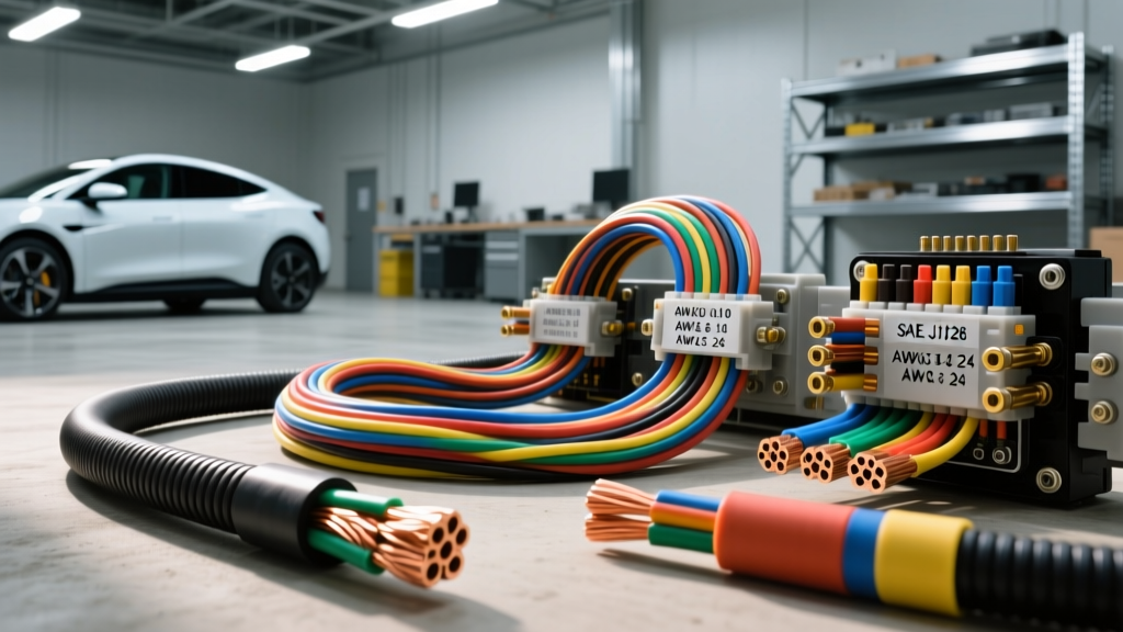
The Evolution of American Wire Gauge in Modern Automotive Architectures
The transition from traditional 12V internal combustion engine (ICE) platforms to 400V and 800V electric vehicle (EV) architectures has fundamentally altered how electrical engineers approach the American Wire Gauge (AWG) system. While the foundational mathematics of AWG remain unchanged, the application of these gauges in modern vehicles requires a deep understanding of thermal derating, high-frequency skin effects, and stringent insulation standards. At autoflowwire, we bridge the gap between theoretical wire sizing and real-world automotive harness fabrication.
Historically, automotive wiring relied heavily on standard PVC-insulated copper. Today, high-current EV powertrains and multiplexed ECU networks demand precise adherence to SAE International J1128 standards. This advanced technical deep dive explores the physics of AWG, insulation chemistry, and specific harness configurations for modern electric and hybrid vehicles.
The Logarithmic Physics of American Wire Gauge
The American Wire Gauge system is a logarithmic stepped system used to specify the diameter of electrically conducting wire. The critical formula for calculating the diameter of an AWG wire in inches is:
D_n = 0.005 × 92^((36-n)/39)
Where n is the AWG number. Because the scale is logarithmic, a decrease of 3 gauge numbers (e.g., from 12 AWG to 9 AWG) roughly doubles the cross-sectional area and halves the electrical resistance. A decrease of 6 gauge numbers doubles the diameter. This mathematical reality is crucial when calculating voltage drop across long EV battery-to-inverter runs, where even a 0.5V drop at 400 amps can result in massive thermal inefficiencies and wasted energy.
SAE J1128 Insulation Standards: GXL, TXL, and SXL
Standard AWG charts often assume bare copper or generic building wire (like THHN). Automotive environments demand specialized cross-linked polyethylene (XLPE) or polyvinyl chloride (PVC) insulations. According to TE Connectivity automotive specifications and SAE J1128, the insulation type drastically alters the outer diameter (O.D.) and thermal limits of the wire.
- GXL (General Cross-Linked): The industry standard for general automotive wiring. Thinner than standard PVC, allowing for tighter harness routing. Rated for 125°C continuous operation.
- TXL (Thin Cross-Linked): Ultra-thin insulation used in high-density ECU connectors (like 64-pin Bosch ME17 harnesses). Rated for 125°C but offers less mechanical abrasion resistance than GXL.
- SXL (Special Cross-Linked): Thickest XLPE insulation, typically reserved for engine bay routing near exhaust manifolds or turbochargers. Rated for 150°C continuous, with brief spikes to 200°C.
Comprehensive Automotive AWG Specification Chart
The following table details the specifications for stranded automotive copper wire (SAE J1128 GXL). Ampacity ratings are derated for automotive chassis wiring, which accounts for bundling and ambient under-hood temperatures, differing significantly from the NFPA 70 National Electrical Code chassis wiring tables.
| AWG Size | Stranding | Nominal O.D. (GXL) | Resistance (Ω/1000ft @ 20°C) | Max Ampacity (Cabin 25°C) | Max Ampacity (Engine Bay 85°C) |
|---|---|---|---|---|---|
| 18 | 16/30 | 0.067" | 6.51 | 16A | 10A |
| 16 | 26/30 | 0.079" | 4.09 | 22A | 14A |
| 14 | 41/30 | 0.092" | 2.57 | 32A | 20A |
| 12 | 65/30 | 0.112" | 1.62 | 45A | 28A |
| 10 | 105/30 | 0.145" | 1.02 | 60A | 38A |
| 8 | 168/30 | 0.190" | 0.64 | 85A | 55A |
| 4 | 655/30 | 0.295" | 0.25 | 150A | 100A |
| 1/0 | 1064/30 | 0.420" | 0.10 | 240A | 160A |
High-Voltage EV Harnesses: 800V Architectures and Shielding
In modern 800V EV platforms (such as the Hyundai E-GMP or Porsche J1 architecture), the main DC traction cables typically range from 2 AWG to 4/0 AWG. These cables are not standard GXL; they are heavily shielded, orange-jacketed (per ISO 6722-1 for HV identification) XLPE cables designed to prevent electromagnetic interference (EMI) from disrupting the vehicle's low-voltage CAN-FD and Automotive Ethernet networks.
HV Cable Construction and Shielding
A typical 1/0 AWG EV traction cable consists of over 1,000 strands of tinned copper to maximize flexibility. Surrounding the XLPE insulation is a braided copper shield with >90% optical coverage, followed by an aluminum-mylar wrap, and finally the bright orange silicone or XLPE outer jacket. This shielding is critical; without it, the high-frequency switching of the silicon carbide (SiC) inverter would induce fatal noise into the 12V sensor harnesses.
HVIL Pinouts and Connector Specifications
High Voltage Interlock Loop (HVIL) circuits are low-voltage safety mechanisms embedded within the high-voltage connectors. Using an Amphenol or TE Connectivity 2-pole HV connector as an example:
- Main Pins (1 & 2): Carry the 400V-800V DC current. These are sized for 2 AWG or 1/0 AWG wire and require specialized hex-crimp tooling.
- HVIL Pins (3 & 4): Carry a 12V or 5V PWM signal loop. These use 18 AWG or 20 AWG unshielded wire.
- Torque Specs: The M8 terminal lugs on the inverter side for 1/0 AWG cables must be torqued precisely to 22 Nm ± 2 Nm. Under-torquing causes micro-arcing and thermal runaway; over-torquing strips the aluminum busbar threads.
Low-Voltage ECU, CAN-FD, and Twisted Pair Requirements
While HV cables handle the brute force of the powertrain, the nervous system of the vehicle relies on 18 AWG to 22 AWG wiring. Modern Controller Area Network (CAN-FD) and Automotive Ethernet (100BASE-T1) require strict twisted-pair geometries to maintain characteristic impedance (typically 120Ω for CAN, 100Ω for Ethernet).
For a standard Bosch MG1 ECU harness, the CAN-High and CAN-Low wires are usually 20 AWG TXL. The twist rate must be maintained at roughly 1 twist per inch (25mm) up to the exact point of the connector backshell. Untwisting the wires too far back to make crimping easier introduces common-mode noise, resulting in U0100 (Lost Communication with ECM) diagnostic trouble codes.
Real-World Failure Modes and Diagnostic Decision Trees
Understanding American Wire Gauge specs is only half the battle; diagnosing gauge-related failures in the field requires a systematic approach. Below is a diagnostic decision tree for common automotive wire gauge failures.
Symptom: Intermittent ECU Reset Under Heavy Load
- Cause 1: Undersized Ground Wire. Many aftermarket or poorly repaired harnesses use 16 AWG for ECU power grounds. Under heavy alternator load or EV DC-DC converter spikes, the voltage drop across the 16 AWG ground exceeds the ECU's 0.5V threshold, triggering a brownout reset.
Fix: Upgrade ground circuits to 12 AWG GXL and verify chassis ground point torque (typically 10 Nm). - Cause 2: Thermal Degradation of PVC. Standard PVC wire used in older repairs near the exhaust manifold melts, causing short-to-ground.
Fix: Replace with 14 AWG SXL (150°C rated) and add corrugated loom with high-temp tape.
Symptom: HV Contactor Dropout (EV Specific)
- Cause: HVIL Loop High Resistance. The 20 AWG HVIL wire inside the main battery disconnect harness suffers from terminal fretting corrosion. The BMS detects >5Ω resistance in the interlock loop and opens the main contactors for safety.
Fix: Inspect the 20 AWG HVIL pins for green copper oxide. Clean with contact cleaner, apply dielectric grease, and ensure the connector CPA (Connector Position Assurance) lock is fully seated.
Conclusion
Mastering the American Wire Gauge system in an automotive context requires looking beyond the basic diameter charts. By integrating SAE J1128 insulation standards, understanding the logarithmic physics of voltage drop, and respecting the stringent shielding and HVIL requirements of modern EV platforms, technicians and engineers can build harnesses that are safe, reliable, and capable of handling the extreme demands of next-generation vehicles.