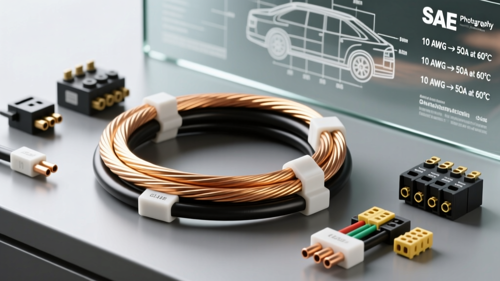
The Short Answer: 10 AWG Amp Capacity in Vehicles
When building a custom harness, upgrading your fuel system, or adding high-draw accessories, knowing exactly how many amps 10 gauge wire is good for is critical to preventing electrical fires and component starvation. In automotive chassis wiring, 10 AWG (American Wire Gauge) stranded copper wire is universally rated for 30 amps of continuous current. For short-burst applications or specialized high-temperature engine bay runs, it can safely handle up to 40 amps before the insulation risks thermal degradation.
However, ampacity is only half the story. In a 12-volt DC environment, voltage drop over distance often dictates your wire size long before the wire's melting point becomes an issue. This guide breaks down the engineering specifications, real-world automotive applications, and termination best practices for 10 AWG wire.
SAE J1128 vs. NEC Building Code: Why the Confusion?
Beginners often search online and find charts rating 10 AWG wire at just 15 or 20 amps. This discrepancy happens because those charts are based on the NEC (National Electrical Code), which governs 120V/240V AC building wire. NEC ratings factor in wires being bundled tightly inside insulated walls, where heat cannot easily escape.
Automotive wiring follows the SAE J1128 Low Tension Primary Cable Standard. Vehicles operate at 12V–14.4V DC, and wires are typically routed through open chassis areas or engine bays where airflow aids cooling. Because of this, SAE standards allow for higher continuous ampacity ratings for the same copper cross-section, provided the correct automotive-grade insulation is used.
Automotive 10 AWG Wire Specification Chart
Not all 10 gauge wire is created equal. The chart below outlines the physical and electrical properties of standard SAE-compliant 10 AWG stranded copper wire.
| Specification | Measurement / Rating |
|---|---|
| AWG Size | 10 AWG |
| Metric Equivalent | 5.0 mm² (Nominal 5.26 mm² actual copper) |
| Standard Stranding | 30 strands of 0.0179" wire (or 105/30 for ultra-flex) |
| Cross-Sectional Area | 5.26 mm² |
| Resistance (at 20°C) | 1.018 Ohms per 1,000 feet |
| Max Continuous Ampacity (Cabin) | 30 Amps |
| Max Continuous Ampacity (Engine Bay) | 25 Amps (due to ambient heat) |
| Recommended Max Fuse | 30A (ATC/ATO or MAXI) |
Real-World Automotive Applications for 10 Gauge Wire
Where exactly should you deploy 10 AWG wire in your car, truck, or hot rod? Here are the most common scenarios where this gauge is the engineering sweet spot.
1. Electronic Fuel Injection (EFI) Fuel Pumps
High-pressure EFI fuel pumps, such as the Walbro 255lph or Bosch 044, typically draw between 12 and 18 amps under load. While 12 AWG wire could technically handle the amperage, the fuel pump relay is often mounted in the cabin while the pump is at the rear axle. Using 10 AWG wire (typically Red with a Black tracer for switched 12V) ensures the pump receives a full 13.8 volts, preventing fuel starvation during wide-open-throttle pulls.
2. High-Draw Electric Cooling Fans
Modern PWM-controlled or high-CFM brushed cooling fans (like dual Spal 11" fans) can pull 20 to 25 amps combined. Running 10 AWG wire from a heavy-duty 30A automotive relay directly to the fan motors ensures the fan spins at maximum RPM when your engine is idling in traffic.
3. Audio Amplifiers (Up to 400W RMS)
A Class D mono-block amplifier pushing 400W RMS into a subwoofer will draw roughly 30 amps at peak output. 10 AWG oxygen-free copper (OFC) power and ground wires are the perfect match for this tier of audio equipment. Always use a 30A ANL or AGU fuse within 18 inches of the battery positive terminal.
4. Winch Solenoid Control Circuits
While the main motor cables on a 10,000 lb winch require 2/0 AWG welding cable, the control solenoids that trigger the winch contactors only draw a fraction of that. 10 AWG is heavily used in the control boxes of heavy-duty off-road rigs to trigger the solenoids reliably without voltage drop.
The Hidden Trap: Voltage Drop and Wire Length
The most common mistake beginners make is sizing wire purely by its melting point. A 10-foot run of 10 AWG wire carrying 30 amps will not catch fire, but it will suffer from voltage drop. According to the Painless Performance Wiring and Fusing Guide, sensitive automotive electronics (like ECU sensors and transmission solenoids) require a minimum of 11.5V to operate correctly. If your wire is too long, the component receives inadequate voltage, leading to erratic behavior.
Voltage Drop Chart for 10 AWG at 30 Amps (12V System)
| One-Way Wire Length | Total Circuit Length (Loop) | Voltage Drop | Resulting Voltage at Load | Verdict |
|---|---|---|---|---|
| 5 Feet | 10 Feet | 0.30V | 12.30V | Excellent |
| 10 Feet | 20 Feet | 0.61V | 12.00V | Acceptable |
| 15 Feet | 30 Feet | 0.91V | 11.70V | Marginal (Upgrade to 8 AWG) |
| 20 Feet | 40 Feet | 1.22V | 11.38V | Fail (Upgrade to 8 AWG) |
Note: Calculations assume a 12.6V resting battery voltage and standard copper resistance at 20°C. If your alternator is charging at 14.2V, the resulting voltage at the load will be proportionally higher.
Insulation Types: GXL, TXL, and SXL Explained
When buying 10 AWG wire, avoid cheap PVC-insulated wire from big-box hardware stores. PVC melts at low temperatures and becomes brittle when exposed to under-hood heat and automotive fluids. Instead, look for Cross-Linked Polyethylene (XLPE) insulation, which is rated for 125°C to 150°C.
- GXL: General Cross-Linked. The standard for aftermarket automotive harnesses. Excellent balance of flexibility, abrasion resistance, and heat tolerance.
- TXL: Thin-Wall Cross-Linked. Features a thinner insulation jacket, saving weight and allowing more wires to fit into tight loom conduits. Ideal for modern ECU repins and dense harness wraps.
- SXL: Special Cross-Linked. Features the thickest insulation jacket. Used in heavy-duty commercial trucks and military applications where extreme abrasion resistance is required.
Termination: Crimping and Fusing 10 AWG Properly
Even the best 10 AWG wire will fail if terminated poorly. A loose crimp creates high resistance, which generates heat and causes voltage drop. Follow these professional termination rules:
The Right Connectors and Tools
For 10 AWG wire, you should be using 8-10 AWG non-insulated ring terminals or Anderson Powerpole SB50 quick-disconnects for modular accessories. Never use generic 'smash' crimpers. Invest in a dedicated hex-crimp tool (such as the Delphi or Weather Pack specific dies). A proper hex crimp cold-welds the copper strands to the terminal barrel, creating a gas-tight seal that prevents oxygen and moisture from causing internal corrosion.
Sealing the Connection
Always use adhesive-lined, dual-wall heat shrink tubing. When heated, the inner layer of hot-melt adhesive flows into the wire strands, creating a waterproof seal that prevents 'green rot' (copper oxidation) from wicking up inside the wire insulation over time.
Fusing Best Practices
The fuse protects the wire, not the component. Because 10 AWG is rated for 30 amps, your fuse should never exceed 30A. If your component draws a continuous 28 amps, a 30A ATC (ATO) blade fuse may experience 'nuisance blowing' due to thermal fatigue in the fuse block. In this scenario, upgrade the wire to 8 AWG and use a 40A MAXI fuse, or use a slow-blow 30A fuse if the initial inrush current of the motor is spiking the circuit.
Summary Checklist for 10 AWG Projects
Before cutting your wire, verify your project against this quick checklist:
- Is the continuous draw under 30 amps?
- Is the one-way wire run under 15 feet? (If longer, calculate voltage drop or step up to 8 AWG).
- Are you using SAE J1128 compliant GXL or TXL wire?
- Are you using a hex-crimp tool and adhesive-lined heat shrink?
- Is the circuit protected by a fuse rated at 30A or less, located within 18 inches of the power source?
By respecting the physical limits and voltage drop characteristics of 10 gauge wire, you ensure your vehicle's electrical system remains reliable, safe, and capable of handling the demands of modern automotive accessories. For more detailed resistance charts and routing guides, refer to the Madsen Automotive Wire Sizing Chart to double-check your specific harness layout.