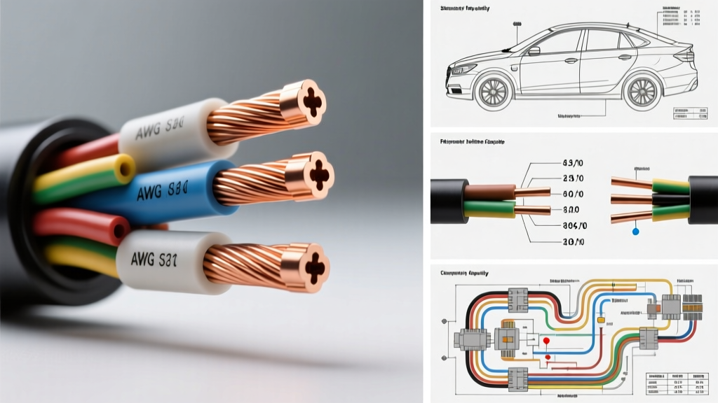
The Physics of Cranking: Power vs. Control Circuits
When evaluating starter wire gauge requirements, it is critical to distinguish between the high-amperage power circuit and the low-amperage control circuit. A modern automotive starter system relies on a solenoid that acts as both a heavy-duty relay and a mechanical engagement fork. The main battery feed (B+ terminal) must deliver massive instantaneous current—often exceeding 350 amps for high-compression V8 engines or heavy-duty diesel applications. Conversely, the control circuit (S terminal) only needs to energize the solenoid's pull-in and hold-in coils, which typically draw between 15 and 30 amps.
Using an undersized starter wire gauge on the main B+ feed results in catastrophic voltage drop, while undersizing the S terminal control wire leads to the infamous 'machine gun' effect (solenoid chatter). Understanding the distinct AWG requirements for each circuit is the foundation of reliable automotive electrical design.
Main Power Circuit (B+ Terminal)
The main power cable connects the battery positive post directly to the starter solenoid's B+ stud. Because cranking is an intermittent, high-load event (typically lasting 2 to 15 seconds), the wire must handle massive current surges without the insulation melting or the voltage dropping below the ECU's operational threshold. For 12-volt systems, this requires a minimum of 4 AWG for standard passenger vehicles, scaling up to 2/0 AWG for heavy-duty diesel or high-compression racing engines.
Control Circuit (S Terminal)
The S terminal receives the 12V start signal from the ignition switch or starter relay. While the amperage draw is low, the wire must still be sized to prevent voltage drop over long chassis runs. A 12 AWG wire is standard for most OEM applications, but upgrading to 10 AWG is recommended in custom builds where the starter relay is mounted in the trunk or rear cabin area.
Ignition Bypass (I and R Terminals)
Older points-style ignition systems utilize an 'I' (Ignition) or 'R' terminal on the solenoid. During cranking, the ignition coil requires a full 12V, bypassing the ballast resistor. This circuit only carries 3 to 5 amps, making 16 AWG or 14 AWG wire perfectly adequate. Note that modern distributorless (COP) and EFI systems do not use the I/R terminal, as the ECU manages fuel and spark independently of the starter solenoid state.
SAE J1127 Battery Cable Specifications
When sourcing cable for a starter wire gauge application, you must specify SAE J1127 compliant battery cable. Do not confuse this with SAE J1128 (primary wire) or standard THHN building wire. SAE J1127 cable is engineered specifically for the harsh under-hood environment, featuring high-strand-count bare copper and EPDM (Ethylene Propylene Diene Monomer) or cross-linked polyethylene (XLPE) insulation rated for 125°C continuous operation.
The high strand count is crucial for flexibility and mitigating the skin effect during high-frequency transients. For example, a genuine SAE J1127 1/0 AWG starter cable contains approximately 4,204 individual strands of 30 AWG bare copper, yielding a nominal cross-sectional area of 53.5 mm². This dense stranding ensures the cable can route through tight chassis clearances without suffering internal strand breakage, a common failure point in cheap, low-strand-count import cables.
Starter Wire Gauge Ampacity & Resistance Chart
The following chart details the specifications for SAE J1127 cables used in starter circuits. 'Max Cranking Amps' reflects a 15-second intermittent duty cycle, which is the standard for automotive starter motor operation.
| AWG Size | Metric (mm²) | Strand Count | Ohms per 1,000 ft (20°C) | Max Continuous Amps | Max Cranking Amps (15s) | Typical Application |
|---|---|---|---|---|---|---|
| 2/0 AWG | 67.4 | 5,320 | 0.0779 | 190A | 600A+ | Heavy Diesel, Supercharged V8 |
| 1/0 AWG | 53.5 | 4,204 | 0.0983 | 150A | 450A | Big Block V8, LS Swaps (High Comp) |
| 2 AWG | 33.6 | 2,646 | 0.1563 | 120A | 350A | Standard V8, Turbo Inline-6 |
| 4 AWG | 21.1 | 1,666 | 0.2485 | 85A | 250A | V6, Inline-4, Gear-Reduction Starters |
| 6 AWG | 13.3 | 1,050 | 0.3951 | 65A | 180A | Small Displacement, Motorcycles, ATVs |
Calculating Voltage Drop in the Starter Circuit
Voltage drop is the enemy of cranking performance. According to Painless Performance Technical Manuals, the maximum acceptable voltage drop for an entire 12V cranking circuit (positive cable + negative ground path) is 1.2 volts. If the voltage at the starter B+ terminal drops below 9.5V during cranking, the ECU may reset, fuel injectors may fail to pulse, and the starter motor torque will plummet exponentially (since DC motor torque is proportional to the square of the voltage).
Voltage Drop Formula
To calculate the expected voltage drop (VD) for a specific starter wire gauge, use the following formula:
VD = (2 × L × I × R) / 1000
- L = One-way length of the cable in feet
- I = Current draw in Amps
- R = Cable resistance per 1,000 ft (from the chart above)
Real-World Calculation: High-Compression V8 Cranking Circuit
Consider a 454ci Big Block Chevrolet with 11:1 compression, drawing 380 amps during cranking. The battery is relocated to the trunk, requiring a 14-foot one-way cable run (28 feet round trip).
- Using 2 AWG Wire: VD = (2 × 14 × 380 × 0.1563) / 1000 = 1.66 Volts. This exceeds the 1.2V SAE limit. The engine will crank sluggishly, and ECU brownouts are highly likely.
- Using 1/0 AWG Wire: VD = (2 × 14 × 380 × 0.0983) / 1000 = 1.04 Volts. This falls safely within the acceptable threshold, ensuring robust cranking RPM and stable ECU voltage.
Terminal Hardware and Crimping Specifications
Selecting the correct starter wire gauge is only half the battle; the termination hardware dictates the reliability of the connection. Starter solenoids typically utilize M8 (5/16') or M10 (3/8') threaded copper or brass studs. Using mismatched ring terminals or improper crimping methods introduces high-resistance points that generate localized I²R heating.
Ring Terminal Sizing and Torque Specifications
| Solenoid Stud Size | Ring Terminal ID | Terminal Material | Required Torque Spec |
|---|---|---|---|
| M8 (5/16') | 8.0mm - 8.4mm | Tinned Copper | 12 - 15 Nm (9 - 11 lb-ft) |
| M10 (3/8') | 10.0mm - 10.5mm | Tinned Copper | 18 - 22 Nm (13 - 16 lb-ft) |
Warning: Never use aluminum or stamped brass ring terminals for high-amperage starter feeds. Always use heavy-wall, tinned copper terminals. Furthermore, indent crimpers are insufficient for cables larger than 6 AWG. You must use a dedicated hex-crimp die (such as those from Astro Pneumatic or Wirex) to ensure uniform compression, eliminating internal voids where copper oxidation can begin.
After crimping, seal the terminal with dual-wall, adhesive-lined heat shrink. The inner meltable adhesive layer flows into the wire strands, creating a hermetic seal that prevents the 'green crust' (copper chloride) caused by under-hood acid vapors and moisture ingress. For deep technical validation on crimping and testing, refer to the Madsen Enterprises Voltage Drop Testing Guide.
Troubleshooting Undersized Starter Wiring
When a starter circuit fails, the symptoms often point directly to incorrect wire gauge selection or degraded connections. Use this diagnostic matrix to identify the root cause:
Symptom: Solenoid Chatter ('Machine Gun' Effect)
- Cause: The main B+ wire gauge is too small, or the battery is weak. When the solenoid pulls in, it connects the main motor contacts. The sudden 300A+ draw collapses the system voltage below the solenoid's holding threshold (typically 7.5V). The solenoid releases, voltage recovers, and it engages again in a rapid, destructive cycle.
- Fix: Upgrade to the next largest AWG starter wire gauge (e.g., from 4 AWG to 2 AWG). Verify the engine-to-chassis ground strap is of equal or greater thickness than the positive cable.
Symptom: Melted Insulation Near the B+ Terminal
- Cause: This is rarely caused by an undersized wire gauge. It is almost always the result of a high-resistance connection at the terminal due to a loose crimp, missing star washer, or incorrect torque. The resistance at the joint generates massive heat (I²R), which melts the insulation from the terminal outward.
- Fix: Cut back the damaged cable, strip fresh copper, and re-terminate using a hex-crimp tool and a new tinned copper ring terminal. Apply dielectric grease to the stud threads to prevent corrosion.
Symptom: Slow Crank but Stable Voltage at Battery
- Cause: Excessive voltage drop across the positive cable or the negative ground path. The wire gauge may be adequate for the distance, but the cable has suffered internal strand corrosion, drastically increasing its resistance.
- Fix: Perform a loaded voltage drop test. Place a multimeter in DC Volts mode. Connect the red probe to the battery positive post and the black probe to the starter B+ stud. Have an assistant crank the engine. A reading above 0.5V on the positive side indicates the cable must be replaced, regardless of its external appearance.
Conclusion: Grounding is Half the Circuit
When upgrading your starter wire gauge, remember that the ground return path is equally critical. Many OEM applications rely on the engine block casting and motor mounts to complete the ground circuit. In high-amperage or aftermarket applications, this is wholly insufficient. Always install a dedicated, braided copper ground strap from the starter mounting bolt (or engine block) directly to the chassis or battery negative terminal. This strap must match the AWG of your positive starter cable to ensure a balanced, low-resistance cranking circuit capable of handling the extreme demands of modern and high-performance engines.