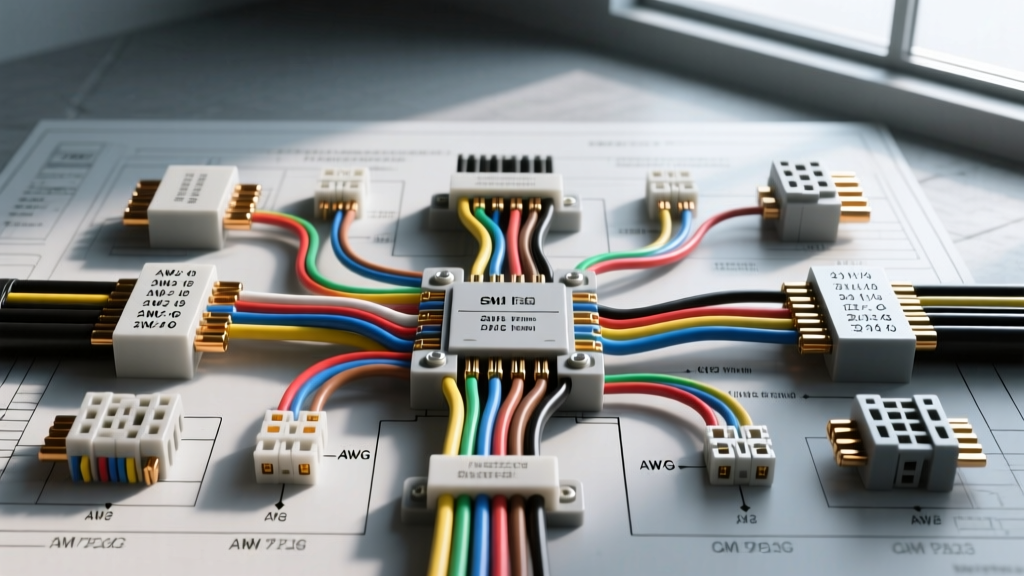
The Danger of Visual Estimation in Automotive Wiring
When diagnosing electrical faults or planning aftermarket upgrades on late-model trucks, guessing wire thickness by sight is a critical error. A 12 AWG and a 14 AWG wire look nearly identical once wrapped in corrugated loom and taped, yet they carry a 20% difference in ampacity. Overloading a 14 AWG circuit with a 15-amp draw will cause severe voltage drop, melted cross-linked polyethylene (TXL) insulation, and potential chassis fires. For technicians and DIYers working on the GM K2XX platform (2014-2018 Silverado 1500/2500HD), knowing exactly how to find wire gauge on factory schematics is the first step in safe, reliable electrical modifications.
Modern factory service manuals rarely use American Wire Gauge (AWG) as the primary measurement. Instead, they rely on metric cross-sectional area (mm²). This guide provides a complete walkthrough of GM Silverado wiring diagrams, teaching you how to extract precise gauge data, trace splice packs, and verify physical wire sizes against SAE standards.
Decoding GM K2XX Silverado Factory Schematics
GM Service Information (GMSI) uses a highly standardized, node-based schematic layout. Unlike older point-to-point diagrams, modern GM schematics separate the physical routing from the logical circuit flow. To determine wire gauge, you must understand the specific text nodes placed directly on the wire lines.
Step 1: Locate the Component and Connector Node
Let us trace the Fuel Pump Control Module (FPCM) power and control circuits on a 2015 Silverado 1500 with the 5.3L EcoTec3 V8. On the schematic, locate the FPCM block. You will see connector designators, typically labeled as X1 (Power/Ground) and X2 (Load/Signal). Each pin cavity is numbered or lettered. For example, Connector X1, Pin A is the primary Battery Feed, while Pin B is the Chassis Ground.
Step 2: Interpret the Wire Size and Color Notation
Look at the line extending from X1 Pin A. Printed directly above or below this line is a string of alphanumeric characters. On a GM diagram, you will typically see a notation like 5.0 RED or 5.0 (10) RED.
- 5.0: This is the cross-sectional area of the copper conductor in square millimeters (mm²).
- (10): If present, this is the AWG equivalent provided as a courtesy by the engineering team.
- RED: The base color of the wire insulation.
If the wire has a tracer (stripe), it will be denoted with a slash or a secondary color code, such as 2.0 BLK/WHT (2.0mm², Black base with a White tracer). Therefore, the FPCM main power feed is a 10 AWG Red wire, and the ground is a 10 AWG Black/White wire. Moving to Connector X2 Pin F (Fuel Pump Supply), the diagram reads 2.0 GRY, indicating a 14 AWG Gray wire feeding the actual pump motor in the tank module (Connector X400).
The Metric-to-AWG Conversion Matrix
Because GM, Ford, and most import manufacturers design harnesses using metric standards (often aligning with ISO 6722 or JIS C 3406), you must convert mm² to AWG to select the correct crimp terminals, heat shrink, and circuit breakers. Below is the definitive conversion chart for standard automotive stranded wire.
| Metric Size (mm²) | AWG Equivalent | Typical Strand Count | Max Ampacity (Chassis) | Common GM Application |
|---|---|---|---|---|
| 0.35 | 22 | 7 | 3A | CAN-Bus High/Low, Sensor Signals |
| 0.50 | 20 | 19 | 5A | ECM Injector Drivers, Low-Current Sensors |
| 0.80 | 18 | 19 | 8A | Interior Lighting, Relay Coils, HVAC Controls |
| 1.25 | 16 | 19 | 12A | Fuel Injectors, Ignition Coils, Power Windows |
| 2.00 | 14 | 19 | 18A | Fuel Pump Feed, ABS Module Signals, Horns |
| 3.00 | 12 | 19 | 25A | Cigarette Lighter, Power Seats, Rear Defogger |
| 5.00 | 10 | 19 | 40A | ECM Main Power, FPCM Feed, Cooling Fans |
| 8.00 | 8 | 19 | 60A | Alternator Output, High-Amp Fuse Block Feeds |
| 13.00 | 6 | 19 | 80A | Glow Plug Controllers (Duramax), Winch Relays |
| 19.00 | 4 | 37 | 120A | Alternator to Battery Positive, Starter Motor |
Note: Ampacity ratings assume single wires in free air at 105°C ambient. Bundled wires inside a harness require a 20-30% derating factor due to trapped heat.
Step 3: Tracing Splice Packs (SP) and Grounds (G)
A common point of confusion when learning how to find wire gauge on complex diagrams is the sudden change in wire thickness mid-circuit. This occurs at Splice Packs (SP) and Grounding nodes (G).
Real-World Example: SP205 Underhood Bussed Electrical Center
Trace the main ignition feed from the Underhood Fuse Block. The schematic shows a massive 13.0 RED (6 AWG) wire leaving the fuse block and entering a node labeled SP205. From SP205, three separate lines emerge, all labeled 2.0 PNK (14 AWG Pink).
This is a physical bussed splice connector hidden deep in the engine harness. The 6 AWG feed carries the combined current for all three downstream circuits (up to 45A total). At the splice pack, the current divides, and the harness manufacturer steps down to 14 AWG for the individual branches to save weight and copper. If you are tapping into the Pink wire for an aftermarket relay trigger, you must use the 14 AWG (18A) rating, not the 6 AWG rating of the upstream feed. Always trace the wire from the load back to the first splice pack or fuse to determine the true gauge of the branch you are modifying.
Physical Verification: When the Diagram is Missing or Modified
Factory diagrams represent the vehicle as it left the assembly line. If you are working on a fleet truck, a plow-prep Silverado, or a vehicle with previous aftermarket repairs, the physical wire may not match the schematic. In these cases, physical measurement is mandatory.
Measuring Stranded Automotive Wire to SAE J1128
Automotive wire is manufactured to SAE J1128 standards for low-tension primary cable, specifically using Thin-Wall (TXL) or General Purpose (GXL) cross-linked insulation. You cannot simply measure the outside diameter of the wire with calipers, as insulation thickness varies by manufacturer.
- Strip the Insulation: Carefully strip back 1 inch of the TXL insulation using a precision wire stripper to avoid nicking the copper strands.
- Fan the Strands: Gently fan out the copper strands so they are not tightly twisted.
- Measure a Single Strand: Use a digital micrometer to measure the diameter of one individual copper strand. For a standard 14 AWG (2.0mm²) wire, a single strand will measure approximately 0.36mm (0.014 inches).
- Calculate Cross-Section: Use the formula
Area = (π/4) × d² × N(where d is strand diameter and N is strand count). Alternatively, compare the overall copper bundle diameter to a known automotive electrical reference chart.
If the wire has been replaced by a previous technician with household solid-core THHN wire from a hardware store, discard it immediately. Solid-core wire cannot withstand the high-frequency vibration of a Silverado chassis and will work-harden, snap, and short against the chassis within months.
Summary References
Mastering schematic literacy is non-negotiable for modern automotive electrical work. By understanding GM's metric notation system, utilizing a reliable mm²-to-AWG conversion matrix, and physically verifying wire integrity against SAE standards, you ensure that every repair and modification maintains the safety margins engineered into the vehicle. Always consult the latest factory service information and adhere to IPC/WHMA-A-620 standards for automotive wire crimping and termination.