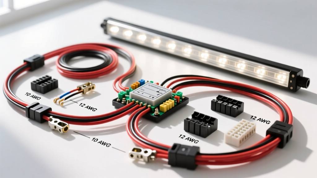
Introduction: The Hidden Dangers of Undersized Lighting Circuits
When mounting a high-output LED light bar on a truck or off-road rig, the most common installation mistake isn't mechanical—it is electrical. Determining what gauge wire for light bar applications is necessary goes far beyond simply matching the physical size of the factory harness. Modern off-road light bars, whether they are 50-inch curved roof racks or 20-inch bumper pods, draw substantial continuous current. Using undersized wiring leads to severe voltage drop, premature LED driver failure, melted insulation, and in worst-case scenarios, electrical fires.
Furthermore, many budget wiring kits sold online utilize Copper Clad Aluminum (CCA) wire instead of pure Oxygen-Free Copper (OFC). CCA wire has roughly 40% higher electrical resistance than pure copper, meaning a 12 AWG CCA wire performs closer to a 14 AWG copper wire. In this complete wiring diagram walkthrough, we will trace a standard automotive relay-controlled light bar circuit from the battery to the chassis ground. We will break down the exact American Wire Gauge (AWG) requirements for both the high-current load circuit and the low-current switch circuit, referencing SAE J1128 low-tension primary cable standards to ensure your installation is safe, efficient, and road-legal.
The Complete Light Bar Wiring Diagram Walkthrough
A proper light bar installation never runs the full load current through the dashboard switch. Instead, it utilizes a standard ISO Mini (Bosch-style) 4-pin automotive relay to isolate the high-amperage load from the low-amperage control circuit. Here is the step-by-step diagram trace:
- Power Feed (Battery to Relay): Heavy-gauge wire runs from the positive battery terminal to an inline fuse, then to Pin 30 of the relay.
- Load Feed (Relay to Light Bar): Heavy-gauge wire runs from Pin 87 of the relay directly to the positive input of the light bar's Deutsch connector.
- Main Ground (Light Bar to Chassis): Heavy-gauge wire runs from the light bar's negative input to a clean, bare-metal grounding point on the chassis.
- Control Feed (Switch to Relay): Light-gauge wire runs from a switched 12V source (like an upfitter switch or ignition circuit) through a dashboard toggle switch, and into Pin 86 of the relay.
- Control Ground (Relay to Chassis): Light-gauge wire runs from Pin 85 of the relay to a local chassis ground.
Because the load circuit (Pins 30 and 87) carries the full amperage of the LED array, it dictates the answer to what gauge wire for light bar setups is required. The control circuit (Pins 85 and 86) only carries the current required to energize the relay's internal electromagnetic coil, which is typically less than 0.20 amps.
Calculating Amperage and Selecting the Correct AWG
To select the correct wire gauge, you must first calculate the maximum amperage draw of your specific light bar. The formula is straightforward: Watts / Volts = Amps. While a resting vehicle battery sits at 12.0V, a running alternator outputs between 13.8V and 14.4V. For conservative wire sizing and fuse selection, always calculate using the lower 12.0V baseline to account for voltage drop and idle conditions.
For example, a popular 50-inch dual-row LED light bar rated at 288 Watts will draw 24 Amps (288W / 12V = 24A). According to standard ampacity charts, 12 AWG wire is rated for 20A to 25A depending on insulation type. However, in automotive applications, wire length drastically affects voltage drop. To maintain a voltage drop of less than 3% (critical for LED driver longevity), you must increase the wire thickness as the run length increases.
Light Bar Wattage to Wire Gauge Reference Chart
| Light Bar Wattage | Max Amperage (at 12V) | Recommended AWG (Under 10 ft Run) | Recommended AWG (10 ft - 20 ft Run) | Required Inline Fuse |
|---|---|---|---|---|
| 36W - 72W (Pods) | 3A - 6A | 16 AWG | 14 AWG | 10A |
| 120W - 180W (20"-30") | 10A - 15A | 14 AWG | 12 AWG | 20A |
| 240W - 300W (40"-50") | 20A - 25A | 12 AWG | 10 AWG | 30A |
| 400W - 520W (60" Roof) | 33A - 43A | 10 AWG | 8 AWG | 50A |
Note: Always use stranded, multi-strand copper wire rated for automotive use. Solid core household wire (THHN) will fracture under engine bay vibrations. Look for GXL or TXL wire, which features thin-wall, high-temperature cross-linked polyethylene insulation that resists melting against hot engine components, as outlined by Del City Wire's automotive specifications.
Fusing Continuous Loads
LED light bars are considered continuous loads. Automotive electrical standards dictate that a fuse should be rated at 125% of the continuous draw to prevent nuisance blowing during thermal cycling or minor voltage sags. If your light bar draws 24A, multiply by 1.25 to get 30A. Therefore, a 30A inline AGU or MAXI fuse is required, placed within 18 inches of the positive battery terminal.
Relay Pinout and Control Circuit Specifications
While the load circuit demands heavy-gauge wire, the control circuit allows for much smaller, more flexible wiring. This makes routing wires through the firewall and under the dashboard significantly easier. Below is the standard pinout for a Bosch-style ISO Mini 4-pin relay, including the recommended wire gauges and standard SAE color codes.
| Relay Pin | Function | Circuit Type | Recommended AWG | Standard Wire Color |
|---|---|---|---|---|
| Pin 30 | Common Power Input | High Current Load | 10 or 12 AWG | Red |
| Pin 87 | Normally Open (NO) Output | High Current Load | 10 or 12 AWG | Red (or Blue) |
| Pin 86 | Coil Power Input (from Switch) | Low Current Control | 18 AWG | White (or Yellow) |
| Pin 85 | Coil Ground | Low Current Control | 18 AWG | Black |
By utilizing 18 AWG primary wire for Pins 85 and 86, you reduce the bulk of the wiring harness passing through the vehicle's firewall grommet. The switch itself only needs to handle roughly 0.15 Amps, meaning standard 15A-rated automotive toggle or rocker switches will run exceptionally cool and last for decades.
Connectors, Terminations, and Real-World Troubleshooting
Knowing what gauge wire for light bar installations is correct is only half the battle; how you terminate that wire dictates the long-term reliability of the system. The harsh environments of off-road driving—water, mud, salt, and extreme vibration—will quickly destroy poor connections.
The Light Bar Connection: Deutsch DT Series
Never splice directly into the light bar's internal pigtails. High-quality light bars utilize Hella-standard or Deutsch DT connectors. The DT series is rated for 20 Amps per pin and features silicone rear seals and wedgelocks that prevent pins from backing out. When crimping 10 or 12 AWG wire to Deutsch pins, always use a closed-barrel pneumatic or ratcheting hand crimper, followed by adhesive-lined marine-grade heat shrink to seal the wire entry point against moisture wicking.
Chassis Grounding Best Practices
Voltage drop on the ground side is just as damaging as voltage drop on the power side. When grounding the light bar or Pin 85 of the relay:
- Remove all paint, powder coating, and rust down to bare, shiny metal using a wire wheel or sandpaper.
- Use a closed-loop ring terminal, never a spade or fork terminal, to prevent the wire from vibrating loose.
- Secure the terminal with a stainless steel bolt, a star washer (to bite into the metal), and a nylock nut.
- Coat the entire finished ground connection in dielectric grease or fluid film to prevent galvanic corrosion.
Troubleshooting Dim Light Bars
If your light bar is installed but appears dim or flickers at idle, you are experiencing voltage drop. Use a digital multimeter to measure the voltage directly at the light bar's Deutsch connector while the lights are on. If you read 12.5V at the battery but only 11.2V at the light bar, you have a 1.3V drop. This is typically caused by undersized wire (e.g., using 14 AWG instead of 10 AWG for a 50-inch bar), a corroded inline fuse holder, or a poor chassis ground. Upgrading the main power and ground runs to 8 AWG or 10 AWG pure copper wire will immediately resolve the issue and restore full lumen output.