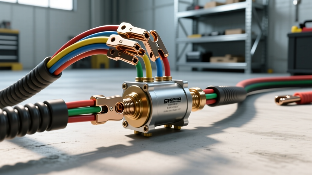
Introduction to 8 AWG in High-Current Automotive Circuits
When designing auxiliary power systems for overland vehicles, RVs, or marine applications, selecting the correct conductor size is critical for both efficiency and fire prevention. The 8 AWG (American Wire Gauge) wire occupies a unique sweet spot in automotive electrical architecture. It is thick enough to handle substantial continuous loads, yet flexible enough to route through complex chassis pathways without requiring specialized hydraulic crimping equipment. In this comprehensive guide, we will explore the exact 8 gauge wire amps rating according to SAE standards and walk through a complete, real-world wiring diagram for a 50A DC-DC charger and continuous duty solenoid setup.
Understanding the limitations and capabilities of 8 AWG copper wire requires looking beyond generic household electrical charts. Automotive environments introduce extreme temperature fluctuations, vibration, and bundled harness constraints that drastically alter a wire's current-carrying capacity. By the end of this walkthrough, you will know exactly how to size, route, crimp, and protect an 8 AWG circuit in a 12V or 24V mobile platform.
Core Question: How Many 8 Gauge Wire Amps Can You Safely Run?
The ampacity of a wire is not a fixed number; it is a variable dependent on insulation type, ambient temperature, and whether the wire is routed in free air or bundled within a harness. According to the SAE J1128 Low Tension Primary Cable Standard, the allowable ampacity for chassis wiring differs significantly from the National Electrical Code (NEC) used in residential buildings.
Standard 8 AWG automotive wire (typically Type SXL or TXL) features a cross-sectional area of approximately 8.37 mm² and a conductor diameter of 0.1285 inches. A high-quality SAE J1127 battery cable in 8 AWG contains 168 strands of 30 AWG copper, providing excellent flexibility. Below is the definitive reference chart for 8 gauge wire amps across varying automotive conditions.
| Routing Environment | Insulation Rating | Max Continuous Ampacity | Recommended Fuse Size |
|---|---|---|---|
| Single Wire in Free Air (Engine Bay) | 60°C (140°F) | 73 Amps | 60A or 70A MIDI/AME |
| Single Wire in Free Air (Cabin) | 75°C (167°F) | 85 Amps | 80A ANL |
| Bundled in Harness (3-6 wires) | 60°C (140°F) | 46 Amps | 40A or 50A Circuit Breaker |
| Bundled in Harness (Engine Bay 90°C) | 90°C (194°F) | 54 Amps | 50A Class T Fuse |
As referenced in the Blue Sea Systems Circuit Protection Guide, you must always size your overcurrent protection device (fuse or breaker) based on the lowest ampacity rating of the wire in the circuit, factoring in the highest ambient temperature the wire will encounter. For a 50A DC-DC charger, 8 AWG is perfectly suited provided the run is kept under 15 feet and the wire is not tightly bundled with other high-current conductors.
Complete Wiring Diagram Walkthrough: 50A DC-DC Charger & Solenoid
To contextualize the 8 gauge wire amps rating, let us trace a complete wiring diagram for an overland dual-battery management system. This system utilizes the vehicle's alternator to charge a secondary lithium (LiFePO4) battery bank via a 50A DC-DC charger, gated by a heavy-duty continuous duty solenoid to prevent draining the starter battery when the engine is off.
Component Pinout and Routing Map
- Power Source: Alternator B+ Terminal or Starter Battery Positive Post.
- Isolation Device: 12V Continuous Duty Solenoid (Terminals 30, 87, 85, 86).
- Load Device: 50A DC-DC Battery Charger (Positive In, Negative In, IGN Sense).
- Main Conductor: 8 AWG Tinned Copper, SXL Insulation (Red for Positive, Black for Negative).
Step-by-Step Diagram Trace
Step 1: The Primary Positive Feed (Alternator to Solenoid)
Begin at the alternator B+ post or the main battery positive busbar. Cut a length of Red 8 AWG wire. Crimp a 3/8-inch tinned copper ring terminal on the source end. Route this wire to Terminal 30 (Input) on the continuous duty solenoid. Critical Note: Install a 60A Class T fuse within 7 inches of the positive source to protect this 8 AWG run against dead shorts.
Step 2: Solenoid to DC-DC Charger Positive Input
From Terminal 87 (Output) on the solenoid, run another segment of Red 8 AWG wire to the 'VIN+' or 'Alternator In' terminal on the DC-DC charger. Use a 5/16-inch ring terminal or an Anderson SB50 connector if modular disconnection is required for maintenance. The 8 AWG wire here will carry the full 50A continuous load when the charger is in the bulk absorption phase.
Step 3: The Grounding Circuit (Chassis vs. Direct)
Lithium charging systems demand pristine grounds to maintain accurate voltage sensing. Do not rely on the vehicle chassis for the DC-DC charger ground. Run an 8 AWG Black wire directly from the 'VIN-' terminal on the charger to the negative busbar or the secondary battery negative post. Ensure the Black 8 AWG wire mirrors the exact length of the Red positive wire to maintain balanced resistance.
Step 4: Ignition Sense and Solenoid Coil (Low Current)
While the main power feeds require 8 AWG to handle the 50A load, the control circuit does not. Run a 14 AWG Yellow wire from an ignition-switched 12V source to Terminal 86 on the solenoid. Ground Terminal 85 using a 14 AWG Black wire to the chassis. This creates the electromagnetic field that pulls the heavy-duty contacts closed, allowing the 8 AWG wire to energize the charger.
Connector Selection, Crimping, and Torque Specifications
Handling the maximum 8 gauge wire amps safely requires flawless termination. A poorly crimped 8 AWG terminal will introduce micro-arcing and resistance, leading to localized melting even if the wire itself is sized correctly.
- Terminal Material: Always use tinned copper ring terminals (e.g., Ancor or Molex). Avoid aluminum or brass terminals in high-amperage DC circuits due to galvanic corrosion and higher resistance.
- Crimping Tool: Use a heavy-duty hex-crimp or indent-crimp tool designed for 8 AWG (such as the Knipex 97 53 14 or a hydraulic crimper). Ratcheting pliers meant for 12 AWG will not provide sufficient deformation for 8 AWG strand compaction.
- Heat Shrink: Seal every termination with 3:1 ratio dual-wall adhesive heat shrink. The inner meltable adhesive layer prevents moisture ingress, which is vital for under-hood routing where salt and water are prevalent.
- Torque Specifications: When securing 3/8-inch (M10) ring terminals to a copper busbar or battery post, apply exactly 10 to 12 Nm (8 to 9 lb-ft) of torque. Under-torquing causes voltage drop; over-torquing can shear the terminal stud or distort the copper ring, reducing the contact patch.
Voltage Drop Calculations and Routing Best Practices
The Victron Energy Wiring Overview mandates that voltage drop in critical charging circuits should not exceed 2% to 3%. Because 8 AWG wire has a resistance of approximately 0.000628 ohms per foot, we can calculate the exact voltage drop for our 50A DC-DC charger setup.
Assuming a total round-trip wire length (positive plus negative) of 20 feet:
Resistance = 20 ft × 0.000628 ohms/ft = 0.01256 ohms.
Voltage Drop = Current × Resistance = 50A × 0.01256 ohms = 0.628 Volts.
On a 14.4V alternator system, a 0.628V drop represents a 4.3% loss. This is slightly above the ideal 3% threshold. To correct this without stepping up to a much stiffer 6 AWG wire, you must shorten the physical routing distance between the alternator, solenoid, and charger, or ensure the alternator output is regulated to a slightly higher baseline voltage to compensate for the line loss.
Real-World Failure Modes & Troubleshooting
Even when you respect the 8 gauge wire amps limits, environmental factors can cause system degradation. Use this decision tree to diagnose common high-current circuit failures:
- Symptom: DC-DC Charger constantly drops out of bulk charging mode.
Cause: Voltage drop across the 8 AWG wire is tricking the charger into thinking the battery is fully charged.
Fix: Enable the remote voltage sense feature on your charger, running a pair of 18 AWG sense wires directly to the battery terminals to bypass the 8 AWG line loss. - Symptom: Solenoid becomes too hot to touch after 30 minutes of driving.
Cause: Using a standard intermittent-duty starter solenoid instead of a continuous-duty model, or the 8 AWG wire is undersized for a bundled harness run, causing heat buildup.
Fix: Verify the solenoid coil rating and ensure the 8 AWG wire is routed in free air, away from exhaust headers. - Symptom: Melted insulation near the crimp barrel, but the wire is intact.
Cause: Incomplete crimp compression. Strands are loose, creating a high-resistance bottleneck that generates intense localized heat despite the 8 AWG wire's overall capacity.
Fix: Cut back the wire, strip fresh insulation, and re-crimp using a calibrated hydraulic tool. Perform a pull-test to verify mechanical integrity.
By strictly adhering to SAE ampacity charts, utilizing proper crimping methodologies, and understanding the physics of voltage drop, you can reliably deploy 8 AWG wire to manage heavy 50A automotive loads with absolute confidence and safety.