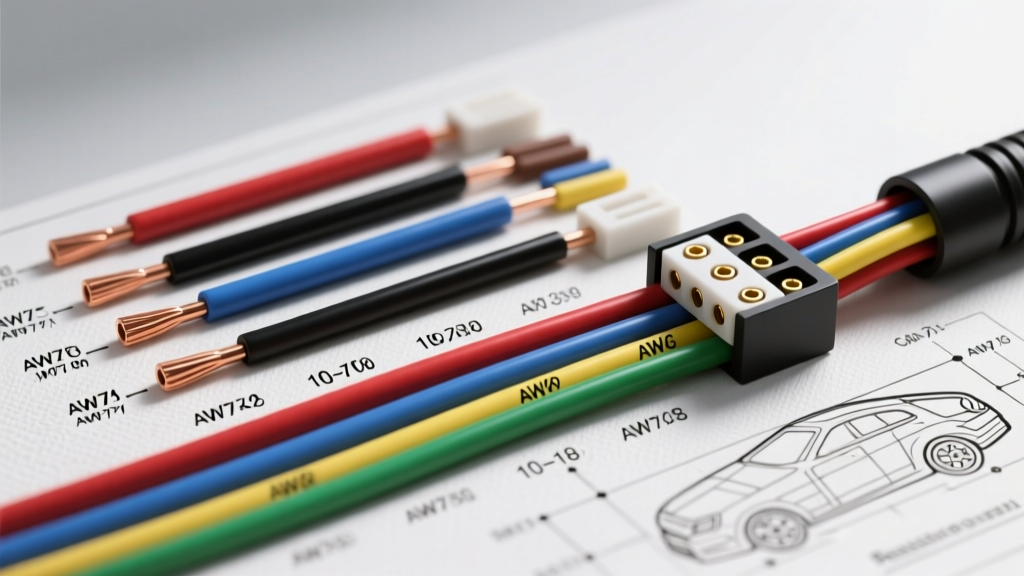
What Defines Automotive Wire Gauge Size?
Understanding the correct wire gauge size is the most critical fundamental skill in automotive electrical diagnostics, repair, and custom fabrication. The American Wire Gauge (AWG) system is the standard used in North America to define the physical diameter and cross-sectional area of electrically conducting wire. For beginners, the most counterintuitive aspect of the AWG system is its inverse relationship: as the gauge number decreases, the physical wire diameter and current-carrying capacity (ampacity) increase. Therefore, a 10 AWG wire is significantly thicker and can handle more current than an 18 AWG wire.
In automotive applications, selecting the proper wire gauge size is not just about preventing blown fuses; it is about managing voltage drop and heat dissipation. The engine bay of a modern vehicle is a hostile environment where ambient temperatures routinely exceed 100°C (212°F). According to the SAE J1128 Standard, which governs low-tension primary cables for automotive use, wire insulation must be rated for specific temperature thresholds, typically 105°C for standard PVC and up to 150°C for cross-linked polyethylene (XLPE). When a wire is undersized for its circuit, electrical resistance generates excess heat, which degrades the insulation, increases resistance further, and ultimately leads to catastrophic short circuits or electrical fires.
The Core 10-18 AWG Wire Gauge Size Reference Chart
The vast majority of automotive accessory wiring, sensor circuits, and lighting feeds fall within the 10 AWG to 18 AWG range. The chart below outlines the critical specifications for these sizes, based on copper conductors with a standard 60°C ambient temperature rating. Always derate ampacity by 20-30% if routing wires through high-heat zones like the exhaust tunnel or directly above the intake manifold.
| AWG Size | Cross-Section (mm²) | Max Ampacity (60°C) | Resistance (Ω/1000ft) | Common Automotive Applications |
|---|---|---|---|---|
| 10 AWG | 5.26 mm² | 30 Amps | 1.018 Ω | Main power feeds, winch relays, high-amperage cooling fans, alternator outputs. |
| 12 AWG | 3.31 mm² | 20 Amps | 1.619 Ω | Fuel pump modules, headlight high-beam feeds, horn relays, power seat motors. |
| 14 AWG | 2.08 mm² | 15 Amps | 2.575 Ω | Tail lights, power window switches, cigarette lighter sockets, HVAC blower motors. |
| 16 AWG | 1.31 mm² | 10 Amps | 4.094 Ω | Dash illumination, ECU sensor grounds, low-draw solenoids, interior dome lights. |
| 18 AWG | 0.82 mm² | 6 Amps | 6.510 Ω | O2 sensor signals, MAF sensors, CAN bus communication lines, injector pulses. |
Decoding SAE J1128 Wire Color Codes
While custom harness builders often use their own color logic, OEM automotive manufacturers adhere to standardized color codes to streamline assembly line production and dealership diagnostics. The most universally recognized standard is the trailer and lighting color code, which often bleeds into the vehicle's internal lighting harness:
- Brown: Running lights, tail lights, and license plate illumination.
- Dark Green: Right rear stop and turn signal.
- Yellow: Left rear stop and turn signal.
- White: Primary chassis ground (though black is also heavily used for general 12V ground returns).
For power distribution, Red is universally reserved for constant battery voltage (B+), while Pink or Orange frequently denotes ignition-switched power (accessory or run positions). When working on modern OBD-II compliant vehicles (1996 and newer), you will frequently encounter twisted pair wiring for the CAN (Controller Area Network) bus. These are typically 18 AWG or 20 AWG wires, often colored CAN High (typically Green or Orange/White) and CAN Low (typically Blue or Orange/Black). Never splice into CAN bus wires with standard crimp connectors; the introduction of even a few millimeters of untwisted wire can alter the characteristic impedance of the bus, causing phantom communication codes (e.g., U0100 Lost Communication with ECM).
Matching Connectors to Your Wire Gauge Size
Selecting the correct wire gauge size is only half the battle; the terminal and connector housing must perfectly match the wire's insulation diameter and conductor crimp depth. Mismatched terminals lead to high-resistance connections, which manifest as localized melting at the connector face. According to Aptiv Connection Systems engineering specifications, terminal grip ranges are strictly defined:
- 10-12 AWG: Requires heavy-duty connectors such as the Weather-Pack series (using blue or orange silicone seals) or large Metri-Pack 630 series terminals. For ring terminals grounding to the chassis, use M8 or M10 studs with a yellow crimp die (indicating 12-10 AWG). Torque ground bolts to 10-15 Nm depending on stud size to ensure metal-to-metal contact without stripping the threads.
- 14-16 AWG: The sweet spot for Metri-Pack 150 and 280 series connectors, utilizing green or yellow cavity seals. These are the workhorses of automotive lighting and accessory circuits. Use a blue crimp die for standard butt splices and ring terminals.
- 18-22 AWG: Requires precision micro-terminals like the Metri-Pack 100W or Deutsch DT series (using green wedgelocks and green cavity seals). When crimping 18 AWG sensor wires, always use a ratcheting micro-crimp tool with a red die. A poorly crimped 18 AWG wire inside a weather-sealed connector will wick moisture via capillary action, leading to green corrosion (copper oxide) that disrupts low-voltage sensor signals.
Real-World Failure Modes and Voltage Drop
The most common beginner mistake is sizing a wire based solely on its maximum ampacity rating while ignoring the total length of the circuit. Wire acts as a resistor. As the length of the wire increases, so does its total resistance, leading to voltage drop. If a fuel pump requires 13.5V to maintain proper rail pressure, but an undersized or excessively long 14 AWG wire causes a 3-volt drop, the pump only receives 10.5V. This results in a lean fuel condition, poor acceleration, and potentially a P0171 (System Too Lean) diagnostic trouble code.
To calculate voltage drop, use the standard formula:
Voltage Drop (Vd) = (2 x L x R x I) / 1000
- L = Total length of the wire in feet (out and back, so multiply one-way distance by 2).
- R = Resistance per 1000 feet of the specific wire gauge size (from the chart above).
- I = Current draw in Amps.
Practical Example: You are wiring a 10-Amp auxiliary light relay using 14 AWG wire. The one-way distance from the battery to the relay and then to the ground is 15 feet (Total L = 30 feet). The resistance (R) for 14 AWG is 2.575 Ω/kft.
Vd = (2 x 15 x 2.575 x 10) / 1000 = 0.77 Volts.
A 0.77V drop on a 12V system is perfectly acceptable (industry standard dictates keeping voltage drop under 3% for critical circuits and under 5% for general accessories). However, if you attempted this same 30-foot run with 18 AWG wire (R = 6.510), the voltage drop would be 1.95 Volts, leaving your lights dim and potentially causing the relay coil to chatter due to insufficient holding voltage.
For high-quality copper wire options and detailed resistance tables, resources like Belden Automotive Wire provide extensive engineering data sheets. Always invest in 99.9% pure oxygen-free copper (OFC) wire rather than copper-clad aluminum (CCA). CCA wire has a higher resistance per foot and is highly prone to galvanic corrosion when crimped inside standard brass or tin-plated automotive terminals, leading to premature circuit failure.