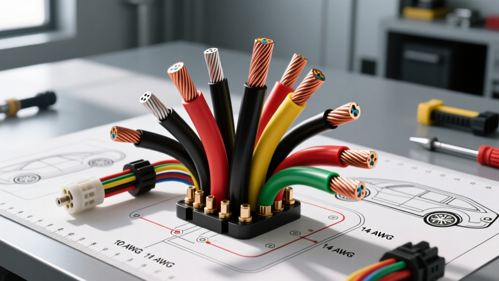
The Critical Role of Wire Gauge Diameters in Automotive Wiring
When installing high-current automotive accessories—such as a 12,000-lb electric winch, a dual-battery isolation system, or a high-output alternator upgrade—most DIYers and technicians focus exclusively on the American Wire Gauge (AWG) number. However, relying solely on the AWG stamp printed on the jacket is a common pitfall. The physical wire gauge diameters, including both the bare copper cross-section and the outer insulation jacket, dictate your routing strategy, grommet selection, heat shrink sizing, and crimp die calibration.
Automotive environments demand rigorous adherence to physical tolerances. A cable routed through a firewall without accounting for its true jacket diameter will suffer from insulation abrasion, leading to a dead short against the chassis. Similarly, mismatching your termination hardware to the physical wire gauge diameters results in high-resistance connections that melt under load. This practical installation guide breaks down how to measure, route, and terminate heavy-gauge automotive cables based on their true physical dimensions.
Understanding AWG vs. SAE Wire Gauge Diameters
The AWG standard strictly defines the cross-sectional area of the conductive metal (usually copper). It does not account for the insulation. In automotive applications, wire is typically manufactured to SAE J1128 standards (such as GXL, TXL, or HDT wire) or as flexible battery cable (SAE J1102). The insulation thickness varies wildly between these types, drastically altering the overall wire gauge diameters you must accommodate during installation.
For instance, a 4 AWG SAE GXL wire features a thin, hard PVC jacket designed for tight engine bay routing, while a 4 AWG flexible welding or battery cable features a thick, flexible EPDM rubber jacket to withstand high vibration and heat. If you attempt to use the same firewall grommet or heat shrink tubing for both, one will be dangerously loose and the other will not fit.
Reference Chart: Bare Copper vs. Jacketed Wire Gauge Diameters
| AWG Size | Bare Copper Diameter (in / mm) | SAE GXL Jacket Diameter (in / mm) | Flexible Battery Cable Jacket Diameter (in / mm) |
|---|---|---|---|
| 8 AWG | 0.1285 / 3.26 | 0.190 / 4.83 | 0.220 / 5.59 |
| 4 AWG | 0.2043 / 5.19 | 0.290 / 7.37 | 0.340 / 8.64 |
| 2 AWG | 0.2576 / 6.54 | 0.360 / 9.14 | 0.420 / 10.67 |
| 1/0 AWG | 0.3249 / 8.25 | 0.460 / 11.68 | 0.540 / 13.72 |
Source: Data compiled from SAE International J1128 standards and standard battery cable manufacturing specifications.
Step-by-Step Installation: Routing High-Amp Cables
Let us walk through the physical installation of a 1/0 AWG positive battery cable for a secondary battery tray in a truck bed, requiring a firewall or bed-bulkhead penetration.
Step 1: Measuring and Selecting the Firewall Grommet
Never guess the grommet size. Use digital calipers to measure the outer jacket diameter of your specific cable. If you are using a 1/0 AWG flexible battery cable, your calipers will read approximately 0.540 inches (13.72mm). You must select a rubber bulkhead grommet with an inner diameter (I.D.) that is slightly smaller than the cable to ensure a watertight seal, but not so small that the friction strips the jacket during the pull. A grommet with a 12.5mm (approx. 0.49 inch) I.D. is ideal. Lubricate the cable jacket with a silicone-based dielectric grease before pulling it through to prevent micro-tears in the EPDM rubber.
Step 2: Securing the Cable and Preventing Chafing
Heavy-gauge cables carry significant mass. When the vehicle hits a pothole, the momentum of a 1/0 AWG cable can easily break standard zip ties. Secure the cable every 8 to 10 inches using stainless steel P-clips lined with EPDM rubber. Match the P-clip size to the wire gauge diameters; for a 0.540-inch cable, a 5/8-inch (15.8mm) or 3/4-inch P-clip will provide the necessary clamping force without crushing the internal copper stranding.
Termination: Matching Heat Shrink and Lugs to Jacket Diameters
The most common failure point in high-amp automotive wiring is the termination. Moisture ingress causes copper oxidation, which increases resistance and generates catastrophic heat. Proper termination requires matching your adhesive-lined heat shrink and crimp lugs to the exact wire gauge diameters.
Sizing Dual-Wall Polyolefin Heat Shrink
Standard single-wall heat shrink is unacceptable for under-hood or exterior automotive wiring. You must use dual-wall (adhesive-lined) polyolefin heat shrink with a 3:1 or 4:1 shrink ratio. The inner layer of hot-melt adhesive melts and flows into the copper strands, creating a waterproof seal.
To size the heat shrink, measure the outer jacket diameter, not the bare wire. If you are terminating a 2 AWG battery cable with a jacket diameter of 0.420 inches (10.67mm), and the crimp barrel of your ring terminal adds another 0.150 inches of bulk, you need a heat shrink with a pre-shrunk inner diameter of at least 0.600 inches (15.2mm). A standard 3/4-inch (19mm) 3:1 heat shrink will easily slip over the assembly and shrink down tightly to the 0.420-inch jacket, forcing the adhesive out the ends to confirm a complete seal.
Selecting and Crimping Heavy-Duty Lugs
For a 1/0 AWG cable terminating at a heavy-duty busbar or an Anderson SB175 connector, use a 3/8-inch stud size heavy-duty copper ring terminal. When crimping, the physical wire gauge diameters dictate your tooling. Do not use an indent crimper on large-gauge flexible battery cable; indent crimpers are designed for solid or lightly stranded wire. Instead, use a hex-crimp die. A hex crimp applies uniform radial pressure, compressing the copper strands and the terminal barrel into a solid, hexagonal mass, eliminating air pockets where moisture could hide.
Once crimped, torque the 3/8-inch terminal nut to the manufacturer's specification—typically 12 to 15 ft-lbs for brass or copper studs. Over-torquing will stretch the stud and reduce the clamping force over time due to thermal expansion and vibration.
Troubleshooting: Spotting Fake AWG and CCA Wire
The aftermarket is flooded with cheap, imported wiring that lies about its AWG rating. This is particularly prevalent with CCA (Copper-Clad Aluminum) wire. Because aluminum is only about 61% as conductive as copper, manufacturers of CCA wire often have to increase the physical wire gauge diameters to safely carry the same amperage as true Oxygen-Free Copper (OFC). Conversely, fraudulent cables will stamp '4 AWG' on the thick jacket, but the actual copper inside is a skimpy 8 AWG or 10 AWG.
The Caliper Verification Test
Before installing any high-amp cable, strip back one inch of the jacket and measure the bare copper bundle with digital calipers. Refer to the chart above. If your '4 AWG' cable measures 0.128 inches across the bare copper bundle, you have been sold 8 AWG wire disguised in a thick jacket. Installing this wire on a 200-amp circuit will result in severe voltage drop, melted insulation, and potentially an electrical fire. Always verify the bare wire gauge diameters against established industry ampacity and gauge charts before committing to the installation.
Final Inspection and Voltage Drop Testing
After routing, crimping, and sealing your connections based on the correct wire gauge diameters, perform a voltage drop test under load. Set your digital multimeter to DC Volts. Place the red probe on the positive battery post and the black probe on the accessory's positive terminal. Engage the accessory (e.g., spool the winch or crank the secondary starter). A properly sized and terminated cable should show a voltage drop of less than 0.10V per connection point, and no more than 0.50V for the entire length of the positive run. If your drop exceeds this, re-check your crimp compression and ensure your physical wire gauge diameters match the current demands of your specific automotive application.
For further reading on heavy-duty electrical termination standards, consult the Belden Wire & Cable Technical Resources library, which provides extensive data on die selection and compression forces for varying wire gauge diameters.