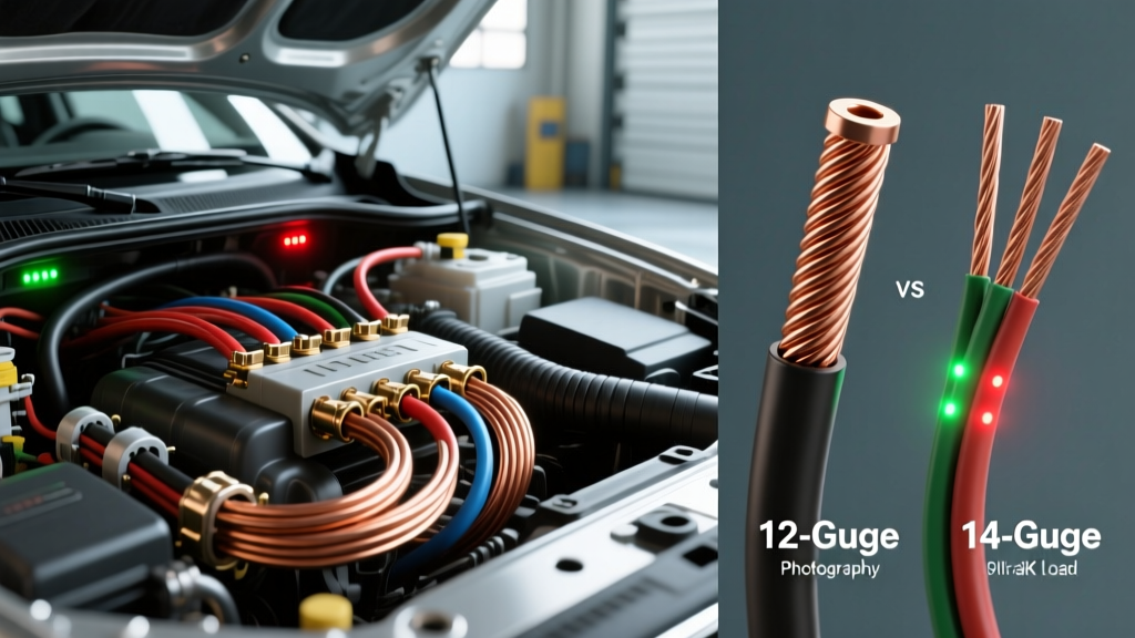
The Short Answer: SAE Limits and Thermal Runaway
When planning a high-draw automotive accessory installation—such as an off-road LED light bar, a winch solenoid, or dual electric cooling fans—a common question arises among DIY mechanics: can 12 gauge wire handle 30 amps? The definitive answer, based on automotive engineering standards, is no. While a bare copper 12 AWG conductor might physically pass 30 amps without instantly snapping, doing so in a real-world automotive environment violates safety margins, causes severe voltage drop, and invites thermal runaway.
According to the SAE J1128 Low Tension Primary Cable Standard, 12 AWG automotive wire (typically GXL or TXL insulation) is rated for a maximum continuous load of roughly 20 to 25 amps, depending on the ambient temperature and whether the wire is bundled in a loom. Pushing 30 amps through a 12 AWG chassis wire generates excessive resistive heat. Under the hood, where ambient temperatures regularly exceed 100°C (212°F) near the exhaust manifold or radiator, the insulation's thermal rating is rapidly approached. The result? Brittle insulation, short circuits against the chassis, and potentially an electrical fire.
To safely and reliably route 30 amps in a vehicle, you must step up to 10 AWG wire. This article analyzes the true cost difference between 12 AWG and 10 AWG setups, the specialized tooling required for high-amp terminations, and the exact wiring protocols for a 30-amp automotive relay circuit.
The Physics of Ampacity and Voltage Drop
Understanding why 12 AWG fails at 30 amps requires looking at electrical resistance. According to Engineering Toolbox AWG Resistance Data, 12 AWG copper wire has a resistance of approximately 1.588 milliohms per foot. In contrast, 10 AWG wire drops to 0.9989 milliohms per foot.
Let us calculate the voltage drop for a 15-foot run from the battery to a 30-amp cooling fan relay, and back to ground (30 feet total circuit length):
- 12 AWG Circuit: 30 ft × 0.001588 ohms = 0.0476 ohms. At 30 amps, Voltage Drop = I × R (30 × 0.0476) = 1.42 Volts.
- 10 AWG Circuit: 30 ft × 0.000998 ohms = 0.0299 ohms. At 30 amps, Voltage Drop = 30 × 0.0299 = 0.89 Volts.
A 1.42-volt drop on a 12V system leaves your accessory receiving only 10.58 volts under load. Electric motors (like cooling fans or fuel pumps) draw more amperage when voltage drops, attempting to maintain their wattage output. This creates a destructive feedback loop: lower voltage causes higher amp draw, which generates more heat in the undersized 12 AWG wire, further increasing resistance and voltage drop until the wire insulation melts or the inline fuse blows.
Cost Analysis: 12 AWG vs. 10 AWG Automotive Wire
Many hobbyists attempt to use 12 AWG wire for 30-amp circuits simply because they already have a spool in their garage, or because they perceive 10 AWG wire to be prohibitively expensive. However, when analyzing the total cost of a properly fused, relay-switched 30A harness, the wire gauge accounts for a surprisingly small percentage of the total build cost.
Material Breakdown for a 30A Accessory Circuit
| Component | 12 AWG Setup (Undersized/Unsafe) | 10 AWG Setup (SAE Compliant) |
|---|---|---|
| Primary Wire (15 ft) | $6.00 (12 AWG GXL Red) | $9.50 (10 AWG GXL Red) |
| Ground Wire (5 ft) | $2.00 (12 AWG GXL Black) | $3.15 (10 AWG GXL Black) |
| Inline Fuse Holder | $4.50 (ATC/ATO Blade Holder) | $8.00 (MAXI Fuse / ANL Holder) |
| Terminals (Ring/Spade) | $3.00 (12-10 AWG Nylon) | $5.50 (10-8 AWG Heavy Duty) |
| Bosch ISO Relay & Socket | $12.00 (Standard 40A Relay) | $12.00 (Standard 40A Relay) |
| Total Material Cost | $27.50 | $38.15 |
As the table illustrates, upgrading to a safe 10 AWG architecture costs roughly $10.65 more per circuit. Given that an electrical fire can total a vehicle, the return on investment for using the correct wire gauge is absolute. Furthermore, 30-amp circuits require MAXI fuses or ANL fuses; standard ATC blade fuses (commonly used with 12 AWG wire) are generally only rated up to 20 or 25 amps, making a 30A ATC fuse a dangerous, non-standard workaround.
Tool Requirements for High-Amp (30A) Terminations
Working with 10 AWG wire requires a step up in tooling. You cannot reliably crimp 10 AWG terminals with standard $15 slip-joint pliers or cheap, non-ratcheting wire crimpers. A poor crimp on a 30-amp circuit introduces localized resistance at the terminal joint, which will become a hot spot and melt the plastic terminal housing.
Essential Tooling Investment
- Ratcheting Crimper (Open Barrel or Closed Barrel): A tool like the IWISS IWS-16 or a Delphi Packard specific crimper is mandatory. Ratcheting crimpers apply a precise, calibrated compression force, ensuring the copper strands are cold-welded to the terminal barrel without crushing or cutting the wire. (Cost: $35 - $60)
- Wire Strippers (8-10 AWG Capacity): Stripping 10 AWG GXL insulation requires a heavy-duty stripper to avoid nicking the outer copper strands. Nicked strands reduce the cross-sectional area of the wire, creating a bottleneck for current flow. (Cost: $20 - $40)
- Dual-Wall Adhesive Heat Shrink: Standard PVC heat shrink is insufficient for under-hood environments. You must use dual-wall polyolefin heat shrink with an inner layer of meltable adhesive. This creates a waterproof seal that prevents galvanic corrosion at the crimp joint. (Cost: $15 per box)
- Heat Gun: A focused heat gun is required to evenly shrink the polyolefin tubing until the adhesive seals out of the ends. (Cost: $25 - $50)
For comprehensive wiring diagrams and professional termination techniques, the Painless Performance Wiring Manuals offer excellent visual guides on achieving proper crimp profiles for heavy-gauge automotive wire.
Real-World Application: Dual Cooling Fan Relay Harness
To put this into practice, let us examine a common 30-amp automotive upgrade: wiring dual 12-inch electric cooling fans (e.g., an LS1 fan swap on a classic muscle car). The startup inrush current for dual fans can easily spike to 35 amps before settling at a continuous draw of roughly 28 amps.
Bosch ISO Mini Relay Pin Configuration
For this setup, a standard Bosch-style ISO mini relay (rated for 40 amps) is used. The pinout dictates which wires carry the heavy load and which carry the low-amp trigger signal:
- Pin 30 (12V+ Constant Input): Must be 10 AWG Red wire, routed directly from the battery positive terminal through a 35A MAXI fuse.
- Pin 87 (12V+ Output to Load): Must be 10 AWG Red wire, routed to the positive terminals of both cooling fans.
- Pin 86 (Relay Coil Trigger): Can be 16 AWG Blue wire, connected to a switched 12V source (e.g., ignition run or thermostat switch).
- Pin 85 (Relay Coil Ground): Can be 16 AWG Black wire, grounded to the chassis.
Notice that the heavy 30-amp current only flows through Pins 30 and 87. If a builder mistakenly uses 12 AWG wire on Pin 30 and Pin 87 to save money or because it is easier to route through the firewall, the wire will overheat. Furthermore, the plastic socket housing the relay will likely melt around the Pin 30 cavity due to the heat transferring from the undersized wire terminal.
Step-by-Step 30A Wiring Protocol
- Disconnect the Battery: Always isolate the negative terminal before cutting or stripping heavy-gauge power wires.
- Measure and Cut 10 AWG Wire: Route the 10 AWG red wire from the battery to the relay location, leaving 6 inches of slack. Avoid sharp exhaust edges and moving steering linkages.
- Strip and Crimp: Strip exactly 5/16 inch of insulation from the 10 AWG wire. Insert into a 10-8 AWG non-insulated ring terminal. Use the ratcheting crimper on the correct die setting to compress the barrel.
- Seal the Joint: Slide a piece of 3/16-inch dual-wall adhesive heat shrink over the terminal and wire. Apply heat until the tubing shrinks tightly and a ring of clear adhesive oozes from the edge.
- Install the MAXI Fuse: Place a 35A MAXI fuse within 18 inches of the battery positive terminal. This ensures that if the 10 AWG wire ever chafes against the chassis, the fuse blows before the wire can catch fire.
- Test Voltage Drop: With the fans running, use a digital multimeter to measure voltage at the battery, and then at the fan motor terminals. The difference should be less than 0.5 volts, confirming your 10 AWG wire is performing optimally.
Conclusion: The Verdict on 12 Gauge and 30 Amps
Returning to the core question: can 12 gauge wire handle 30 amps? In a strictly theoretical, short-duration laboratory test, perhaps. In a practical, high-temperature, vibration-heavy automotive environment, absolutely not. The minor financial savings of using 12 AWG wire are entirely negated by the severe risk of voltage drop, component starvation, and electrical fires. By investing the extra $10 in 10 AWG GXL wire, a ratcheting crimper, and proper adhesive heat shrink, you ensure your high-draw accessories operate reliably for the life of the vehicle.