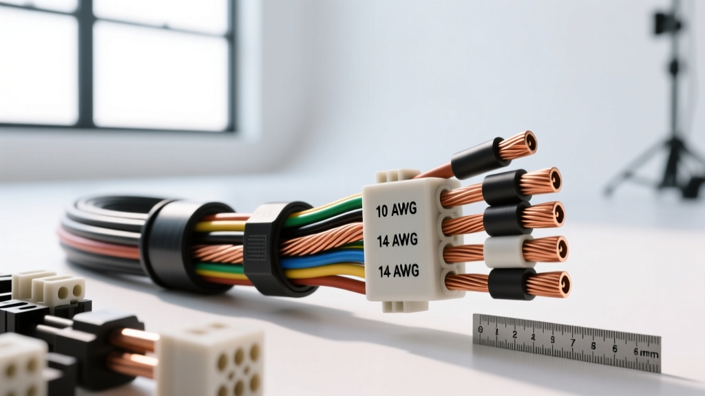
Why Verifying Wire Gauge is Critical for Mod Projects
When executing high-draw automotive electrical upgrades—such as installing a high-output alternator, adding a 12,000 lb winch, or building a custom off-road lighting harness—relying on the printed text on a wire jacket is a rookie mistake. The aftermarket is flooded with mislabeled wiring, particularly Copper Clad Aluminum (CCA) sold as pure Oxygen-Free Copper (OFC). If you are asking, 'how do you measure wire gauge,' you are already ahead of 90% of hobbyists who blindly trust packaging.
Undersized wire in a modification project doesn't just cause voltage drop; it acts as a resistor, generating excessive heat that melts insulation, destroys relay contacts, and causes electrical fires. According to the SAE J1128 standard for low-tension primary automotive cable, wire sizing must account for both the continuous amperage draw and the ambient temperature of the engine bay, which frequently exceeds 125°C (257°F). To ensure your upgrade is safe and efficient, you must physically verify the American Wire Gauge (AWG) of your materials before crimping a single terminal.
How Do You Measure Wire Gauge Accurately in the Field?
Measuring stranded automotive wire requires a slightly different approach than measuring solid household wire. Because stranded wire has microscopic air gaps between the copper filaments, measuring the outer diameter of the bundle will yield a slightly larger reading than the true copper cross-section. Here are the three professional methods to determine exact AWG.
Method 1: The Digital Caliper Technique (Most Accurate)
For the most precise measurement, you need a digital caliper and a bare wire sample.
- Strip the Jacket: Carefully strip exactly 1 inch of insulation from the wire using a precision wire stripper. Do not nick the copper strands, as this alters the diameter.
- Compress the Strands: Tightly twist the exposed stranded bundle to eliminate air gaps, simulating the compression of a closed-barrel crimp terminal.
- Measure the Diameter: Clamp the caliper jaws gently around the bare copper bundle. Record the measurement in both inches and millimeters.
- Cross-Reference: Compare your reading to the AWG reference chart below. For example, a true 4 AWG OFC wire bundle will measure approximately 0.204 inches (5.19 mm) in diameter.
Method 2: The Notched Wire Gauge Tool
If you lack calipers, a dedicated wire gauge measuring tool (a flat metal plate with precision-machined semi-circular notches) is the next best option. Strip the wire and slide the bare copper into the notches. The smallest notch that the wire passes through without binding is your AWG size. Warning: Do not use the stripping holes on a standard pair of wire strippers to measure gauge; these holes are designed to cut insulation and are notoriously inaccurate for measuring bare copper diameters.
Method 3: Measuring Insulated Wire (OD vs. ID)
Sometimes you cannot strip the wire, such as when auditing an existing factory harness or measuring heavy 1/0 AWG battery cables. You must measure the Outer Diameter (OD) and subtract the jacket thickness. High-quality automotive primary wire (like SXL or TXL cross-linked polyethylene) has a thin jacket, while cheap CCA wire often uses a massively thick PVC jacket to create the optical illusion of a larger gauge. If a '4 AWG' wire measures 0.35 inches overall, it is heavily padded and likely 8 AWG or 10 AWG copper inside.
AWG Diameter Reference Chart for Automotive Upgrades
Use this reference chart when verifying your wiring with a digital caliper. Data aligns with standard bare copper strand bundle measurements. For deeper technical specifications on resistance and ampacity, refer to the Engineering Toolbox AWG standards.
| AWG Size | Diameter (Inches) | Diameter (mm) | Typical Mod Application |
|---|---|---|---|
| 1/0 AWG | 0.3648' | 9.26 mm | High-output alternator Big-3 upgrades, EV battery links |
| 2 AWG | 0.2576' | 6.54 mm | Winch power feeds, heavy-duty chassis grounds |
| 4 AWG | 0.2043' | 5.19 mm | Amplifier power feeds (1000W+), air compressor lines |
| 8 AWG | 0.1285' | 3.26 mm | Mid-range amp feeds, off-road light bar main power |
| 10 AWG | 0.1019' | 2.59 mm | Relay Pin 30/87 feeds (30A circuits), fuel pumps |
| 12 AWG | 0.0808' | 2.05 mm | Cigarette lighter accessories, cooling fan relays |
| 14 AWG | 0.0641' | 1.63 mm | Headlight harness upgrades, horn relays |
| 16 AWG | 0.0508' | 1.29 mm | Relay trigger wires (Pins 85/86), ECU sensor grounds |
| 18 AWG | 0.0403' | 1.02 mm | LED indicator lights, low-draw CAN-bus taps |
Common Upgrade Scenarios: Factory vs. Aftermarket Wire
Scenario A: The 'Big 3' Alternator Upgrade
When upgrading a factory 120A alternator to a 250A+ unit for a massive car audio system, the factory 6 AWG or 8 AWG alternator-to-battery wire will bottleneck the system, causing voltage drop and alternator overheating. You must upgrade to 1/0 AWG or 2 AWG OFC wire. Expert Tip: Measure your new 1/0 AWG wire before installation. Many budget brands sell '1/0 AWG Welding Wire' that is actually 2 AWG copper padded with a thick EPDM rubber jacket. While welding wire is flexible and oil-resistant (excellent for engine bays), if it measures 0.257 inches on your caliper, you are getting 2 AWG, not 1/0.
Scenario B: Off-Road Lighting Relay Harnesses
When building a custom relay harness for a 50-inch LED light bar, understanding relay pinouts and wire gauges is critical. A standard Bosch-style 5-pin relay requires specific wire sizes for different circuits:
- Pin 30 (12V+ Input from Battery): 10 AWG (Red wire, fused at 30A).
- Pin 87 (12V+ Output to Light Bar): 10 AWG (Red wire).
- Pin 86 (Trigger 12V+ from switch): 16 AWG (Blue or Yellow wire).
- Pin 85 (Ground): 16 AWG (Black wire, ring terminal to chassis).
- Pin 87a (Normally Closed): Not used in standard lighting; cap with heat shrink.
If you attempt to run the Pin 30 battery feed with 14 AWG wire, the 30-amp draw will push the wire past its safe ampacity limit in an engine bay environment, risking a meltdown before the fuse blows.
Beware of CCA (Copper Clad Aluminum) in Aftermarket Kits
The most crucial reason to learn how do you measure wire gauge is to identify CCA wire masquerading as OFC. CCA wire features an aluminum core with a microscopically thin copper coating. Aluminum has only 61% of the conductivity of copper. Therefore, a 4 AWG CCA wire performs electrically like an 8 AWG pure copper wire, but with a higher risk of galvanic corrosion at the crimp terminals.
The Scratch Test: Take your wire stripper or a utility knife and aggressively scrape the side of a bare copper strand. If the wire is OFC, it will remain copper-colored all the way through. If a silver or white metallic core is revealed, you have CCA. If you are forced to use a CCA kit for a modification project, you must upsize the wire by at least two full AWG gauges (e.g., use 2 AWG CCA to achieve the performance of 4 AWG OFC) to compensate for the increased resistance and prevent voltage drop.
Expert Tips for Crimping and Terminating Measured Wire
Once you have verified your wire gauge, proper termination is mandatory to maintain the integrity of your upgrade. Never use solder on high-vibration automotive wiring; solder wicks into the stranded wire, creating a rigid point that will eventually snap under engine vibration.
- Adhesive-Lined Heat Shrink: Always use marine-grade, adhesive-lined heat shrink terminals. The internal glue melts and seals the wire barrel, preventing oxygen and moisture from causing green copper oxidation (verdigris), which increases resistance over time.
- Hex Crimp vs. Indent Crimp: For wires 8 AWG and larger (like your Big-3 upgrade cables), use a hex-crimp tool rather than a standard indent crimper. Hex crimping compresses the copper strands and terminal barrel into a tight, uniform hexagonal shape, eliminating air pockets and ensuring maximum surface contact for high-amperage transfers.
- Torque Specifications: When securing heavy ring terminals (like 2 AWG battery grounds to the chassis or engine block), clean the metal down to bare steel with a wire wheel, apply a thin layer of dielectric grease over the terminal after tightening, and torque the bolt to factory specifications (typically 15-25 ft-lbs for M8/M10 ground studs) to prevent loosening from thermal cycling.
For comprehensive wiring diagrams and routing best practices, always consult manufacturer-specific guides like those provided in Painless Performance Wiring manuals. By physically measuring your wire and adhering to strict termination protocols, your automotive electrical upgrades will remain safe, reliable, and capable of handling extreme loads for years to come.