Introduction: The Role of 10 AWG in High-Draw Automotive Circuits
When modifying or repairing high-current automotive systems, understanding the exact current-carrying capacity of your wiring harness is critical to preventing electrical fires and component failure. One of the most common questions we receive at the bench is determining the max amperage for 10 gauge wire in a 12V DC automotive environment. While 10 AWG (American Wire Gauge) is a staple for mid-to-high current loads, its true ampacity is heavily dependent on insulation type, ambient temperature, and wire material. In this complete wiring diagram walkthrough, we will trace a heavy-duty dual electric cooling fan relay circuit. By following the schematic from the battery positive terminal to the fan motors and ground planes, we will demonstrate exactly where 10 AWG wire is required, where it falls short, and how to properly terminate it using industry-standard connectors.
What is the Max Amperage for 10 Gauge Wire?
The max amperage for 10 gauge wire is not a single universal number; it is dictated by the governing standard and the operational environment. In residential and commercial AC wiring, the National Electrical Code (NEC) typically rates 10 AWG copper wire at 30 amps. However, automotive environments utilize different standards, primarily SAE J1128, which governs low-tension primary cable. Automotive wire (such as GXL or TXL) features thin-wall, high-temperature cross-linked polyethylene insulation rated up to 125°C or 150°C. Because the insulation can withstand higher heat, automotive 10 AWG stranded copper can safely carry more current over short chassis runs than its NEC building-wire counterpart.
For automotive chassis wiring (short runs under 15 feet in open air), the max amperage for 10 gauge pure copper wire is generally accepted at 40 amps. However, when bundled in a loom with other current-carrying conductors or routed through high-heat engine bay areas, this rating must be derated by 20% to 30%, bringing the safe continuous limit down to roughly 28 to 32 amps. It is also vital to distinguish between Oxygen-Free Copper (OFC) and Copper-Clad Aluminum (CCA). CCA wire has higher electrical resistance and lower tensile strength; a 10 AWG CCA wire will overheat at currents that a 10 AWG OFC wire handles effortlessly. Always verify your wire is 100% stranded copper for high-draw automotive applications.
10 AWG Ampacity & Resistance Specification Chart
| Wire Material & Standard | Insulation Type | Max Temp Rating | Continuous Ampacity (Chassis) | Resistance per 1,000 ft (at 20°C) |
|---|---|---|---|---|
| SAE J1128 (OFC Copper) | GXL (Thin Wall) | 125°C | 40A (Derated to 30A bundled) | 1.018 Ohms |
| SAE J1128 (OFC Copper) | TXL (Extra Thin) | 125°C | 40A (Derated to 30A bundled) | 1.018 Ohms |
| CCA (Copper-Clad Aluminum) | PVC (Standard) | 80°C - 105°C | 25A - 30A (Not recommended for high draw) | ~1.600 Ohms |
| NEC THHN (Building Wire) | PVC / Nylon | 90°C | 40A (AC Reference Only) | 1.210 Ohms (Stranded) |
Diagram Walkthrough: Dual Electric Cooling Fan Relay Circuit
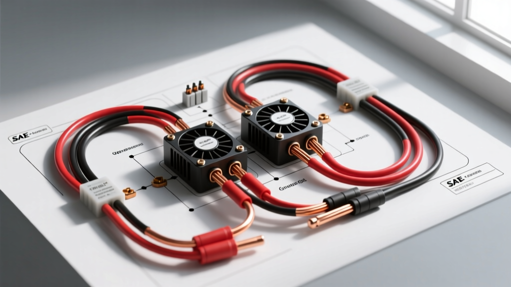
To contextualize the max amperage for 10 gauge wire, let us walk through a wiring diagram for a dual 16-inch electric cooling fan setup, a common upgrade for classic muscle cars and heavy-duty trucks. Each fan motor draws approximately 15 amps on high speed, resulting in a combined continuous draw of 30 amps, with a startup surge (inrush current) that can briefly exceed 45 amps. This circuit requires a robust power feed, a heavy-duty relay, and proper overcurrent protection.
Step 1: The Main Power Feed and Overcurrent Protection
Starting at the battery positive terminal, we route a 10 AWG red OFC wire to a 40-amp mega-fuse or ANL fuse holder mounted within 18 inches of the battery. Because the total continuous draw is 30 amps, and accounting for the inrush current and engine bay heat derating, 10 AWG is the absolute minimum acceptable size. If the run exceeds 15 feet (round trip), the diagram dictates stepping up to 8 AWG to mitigate voltage drop. The 10 AWG red wire is terminated with a 3/8-inch heat-shrink ring terminal and bolted directly to the heavy-duty relay's Pin 30 (Power Input).
Step 2: The Load Side and Fan Pigtails
From Pin 87 (Normally Open Power Output) of the relay, we continue with 10 AWG red wire to a distribution block or a sealed Delphi Weather-Pack splitter. From the splitter, two separate 10 AWG leads route to the positive terminals of Fan 1 and Fan 2. The ground side of the fans utilizes 10 AWG black wire, terminating at a dedicated, bare-metal chassis grounding stud. Using the vehicle's sheet metal as a ground return path for a 30-amp load is a common failure point; the diagram strictly requires a dedicated 10 AWG ground wire bolted directly to the engine block or frame with a star washer to bite through the paint and primer.
Step 3: The Control Circuit (Low Amperage)
The relay coil requires minimal current (typically under 200 milliamps). Therefore, we drop down to 14 AWG or 16 AWG wire for the control side. Pin 85 (Coil Ground) is tied to a clean chassis ground using a 1/4-inch female spade connector. Pin 86 (Coil Trigger) receives a 12V signal from the engine coolant temperature switch or the ECM. This wire is typically colored yellow or blue to differentiate the low-current trigger from the high-current 10 AWG load circuit.
Heavy-Duty ISO Relay Pinout Configuration
| Relay Pin Number | Standard Function | Wire Gauge Required | Wire Color Code | Connection Point |
|---|---|---|---|---|
| Pin 30 | Common / Power Input | 10 AWG (Minimum) | Red | Battery Positive (via 40A Fuse) |
| Pin 87 | Normally Open (NO) Output | 10 AWG (Minimum) | Red | Fan Motor Positive Terminals |
| Pin 86 | Coil Trigger / Signal | 14 AWG or 16 AWG | Yellow / Blue | ECM or Temp Switch Output |
| Pin 85 | Coil Ground | 14 AWG or 16 AWG | Black | Chassis Ground / Engine Block |
Calculating Voltage Drop in 10 AWG Automotive Harnesses
Knowing the max amperage for 10 gauge wire is only half the battle; you must also calculate voltage drop. Electric cooling fans are highly sensitive to voltage. A fan rated to move 2,500 CFM at 13.8V may only move 1,800 CFM if the voltage at the motor drops to 11.5V due to undersized wiring. The formula for voltage drop in a DC circuit is: Voltage Drop = Current (Amps) x Resistance per foot x Total Wire Length (Out and Back).
Using our Del City Wire Ampacity Standards reference, 10 AWG copper has a resistance of roughly 0.001018 ohms per foot. If the distance from the battery to the fans is 10 feet, the total round-trip wire length is 20 feet. At a 30-amp continuous draw, the calculation is: 30A x 0.001018 ohms/ft x 20 ft = 0.61 Volts. A drop of 0.61V on a 13.8V charging system leaves 13.19V at the fan motor, which is well within the acceptable 3% voltage drop threshold for automotive accessories. However, if the routing requires 25 feet of one-way distance (50 feet round trip), the drop increases to 1.52V, leaving only 12.28V at the motor. At this point, the diagram requires upgrading the main feed to 8 AWG wire to maintain optimal fan performance.
Real-World Failure Modes & Troubleshooting 10 AWG Circuits
When diagnosing a failed high-current circuit, technicians often overlook the physical degradation of the 10 AWG wire and its terminations. Below are the most common failure modes encountered when pushing 10 AWG wire to its 30A-40A limits in an engine bay:
- Thermal Cycling and Brittle Insulation: Standard PVC-insulated 10 AWG wire (often found in cheap aftermarket kits) becomes brittle when exposed to engine bay temperatures exceeding 80°C. The insulation cracks, exposing the copper to moisture and causing short circuits. Always specify GXL or TXL cross-linked insulation for under-hood applications.
- Crimp Failure at Pin 30: The high inrush current of dual electric fans generates significant heat at the relay spades. If the 10 AWG ring terminal is crimped with an improper tool (e.g., standard pliers instead of a closed-barrel hex crimp tool), the increased resistance at the joint will cause the relay socket to melt. Always use an adhesive-lined heat shrink crimp terminal and verify the pull-test strength.
- Ground Plane Bottlenecks: A circuit is only as good as its ground. If the 10 AWG black ground wire is bolted to a painted bracket or a rusted frame rail, the resistance will spike. This forces the current to seek alternative paths, often backfeeding through the ECM or lighting harnesses. Use a digital multimeter to perform a voltage drop test across the ground connection while the fans are running; a reading above 0.1V indicates a failing ground termination.
For deeper diagnostic procedures on relay control circuits and coil flyback voltage suppression, refer to the technical guides provided by AA1Car Automotive Relay Diagnostics. Understanding the interplay between wire gauge, insulation thermodynamics, and circuit topology ensures your high-draw automotive modifications remain safe, reliable, and fully functional under extreme operating conditions.