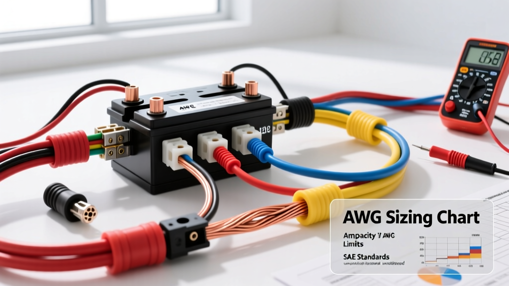
Understanding Parallel 12V Battery Interconnects
When building a dual-battery or multi-battery bank for overlanding, marine, or RV applications, wiring 12V batteries in parallel is the standard method for increasing amp-hour (Ah) capacity while maintaining a nominal 12-volt system. However, the interconnect wiring—the cables that bridge the positive and negative terminals between the batteries—is frequently the most overlooked component in the entire electrical system. If you are asking yourself what gauge wire to connect 12v batteries in parallel, the answer requires a careful analysis of your maximum continuous load, the charging output of your alternator, and the physical routing of the cables.
Unlike a simple accessory circuit, battery interconnects must handle massive bidirectional current flow. They carry the full charging current from the alternator or solar charge controller during the bulk absorption phase, and they must equally distribute discharge current when running high-draw inverters or winches. Undersizing these cables leads to severe voltage drop, unequal battery cycling, and potentially catastrophic thermal events.
What Gauge Wire to Connect 12V Batteries in Parallel?
The fundamental rule of parallel battery wiring is that the interconnect wire gauge must be equal to or larger than the main feed wire gauge that connects the battery bank to the primary busbar or inverter. Many novice installers mistakenly believe that because the interconnect only bridges a short distance of 12 to 24 inches, they can step down the wire gauge. This is a critical error. The interconnect wire must be capable of carrying the entire system load in a worst-case scenario, such as a dead cell in one battery forcing the secondary battery to supply 100 percent of the discharge current.
AWG Sizing and Ampacity Reference Chart
The following table outlines standard American Wire Gauge (AWG) specifications for pure copper conductors, based on SAE J1128 standards for high-temperature automotive and marine environments. Ampacity ratings assume a maximum ambient temperature of 105 degrees Celsius and are derated for enclosed engine compartments or tightly bundled wire runs.
| AWG Size | Max Continuous Amps (105C) | Resistance (Ohms per 1000ft) | Typical Parallel Interconnect Application |
|---|---|---|---|
| 4 AWG | 135A | 0.256 | Light duty dual-battery (e.g., auxiliary fridge, small 800W inverter) |
| 2 AWG | 175A | 0.162 | Standard RV/Overland setups (e.g., 1500W inverter, standard alternator charging) |
| 1/0 AWG | 230A | 0.102 | Heavy duty off-grid (e.g., 2000W inverter, high-output 220A alternator) |
| 2/0 AWG | 265A | 0.081 | High-draw marine/industrial (e.g., 3000W inverter, bow thrusters, winches) |
| 4/0 AWG | 360A | 0.051 | Massive 48V-to-12V conversion banks, extreme duty continuous cycling |
The Diagonal Wiring Method: Critical for Parallel Banks
Knowing what gauge wire to connect 12v batteries in parallel is only half the battle; the topology of the wiring is equally important. When connecting two or more batteries in parallel, you must use the diagonal wiring method. If you connect the main positive and main negative loads to the same battery (post-to-post wiring on the same side), the first battery in the chain will experience the highest current draw and the highest charging voltage. This happens because the current must travel through the interconnect cables—which possess inherent electrical resistance—to reach the second battery.
By wiring diagonally (connecting the main positive load to the positive terminal of Battery A, and the main negative load to the negative terminal of Battery B), the total length of wire the current must travel through the interconnects is perfectly balanced. This ensures that both batteries share the electrical load equally and charge at the exact same rate, drastically extending the lifespan of flooded lead-acid, AGM, or Gel battery banks. For lithium iron phosphate (LiFePO4) batteries equipped with internal Battery Management Systems (BMS), equal resistance is vital to prevent a single BMS from tripping due to over-current conditions.
Calculating Your Specific Wire Gauge Requirement
To determine the exact gauge for your specific build, you must calculate the maximum continuous current your system will demand. According to the American Boat and Yacht Council (ABYC) E-11 standards, continuous loads (defined as currents flowing for more than three minutes) require wiring rated for 100 percent of the load, plus a 20 percent safety margin.
Example Calculation: If you are running a 2000-watt pure sine wave inverter on a 12V nominal system, the maximum continuous draw is calculated by dividing the wattage by the lowest expected operating voltage (usually 11.5V under load), then factoring in inverter efficiency (typically 85 percent).
- 2000W / 11.5V = 173.9 Amps
- 173.9A / 0.85 (efficiency) = 204.6 Amps continuous draw
- 204.6A x 1.20 (safety margin) = 245.5 Amps
Based on this calculation, a 245.5 Amp requirement dictates the use of 1/0 AWG or 2/0 AWG pure copper wire for both the main inverter feed and the parallel battery interconnects. Always reference manufacturer-specific derating charts, such as the Blue Sea Systems Circuit Wizard, to account for voltage drop over longer cable runs.
SAE J1128 Standards and Conductor Materials
When sourcing wire for battery interconnects, the conductor material is just as critical as the gauge. The SAE J1128 standard governs automotive primary wire, specifying requirements for insulation thickness, temperature resistance, and conductor stranding. For high-current parallel battery connections, you should exclusively use SGX (Standard Cross-Linked) or SXL (Special Cross-Linked) battery cable. These insulation types are highly resistant to heat, automotive fluids, and abrasion.
Copper vs. CCA: Never use Copper Clad Aluminum (CCA) wire for high-amperage battery interconnects. While CCA is cheaper and lighter, aluminum has roughly 61 percent of the conductivity of pure copper. A 2 AWG CCA cable will perform electrically closer to a 4 AWG pure copper cable, leading to excessive voltage drop and dangerous heat buildup at the crimp terminals. Always verify that your wire is stamped with 'Pure Copper' or 'OFC' (Oxygen-Free Copper).
Terminal Selection, Crimping, and Torque Specifications
The most common point of failure in a parallel battery bank is not the wire itself, but the terminal connection. High-current interconnects require heavy-duty, closed-barrel copper ring terminals, preferably tinned to resist oxidation. For standard Group 24, 27, and 31 marine/RV batteries, the positive and negative posts typically require a 3/8-inch inner diameter (I.D.) ring terminal. Standard automotive top-post batteries usually require a 5/16-inch I.D. terminal.
Crimping must be performed using a calibrated hex-die or indent-style hydraulic crimper. Soldering high-current battery lugs is heavily discouraged in automotive and marine environments; solder can wick into the wire strands under the insulation, creating a rigid section that is highly susceptible to work-hardening and fracturing from engine vibration.
Sealing and Torque Specs
After crimping, all terminals must be sealed using dual-wall polyolefin heat shrink tubing with an inner adhesive lining. This prevents moisture ingress and halts capillary action that can lead to green copper corrosion creeping under the insulation. When tightening the terminal nuts on the battery posts, adhere strictly to manufacturer torque specifications. Over-torquing a soft lead battery post will strip the threads or crack the battery casing. Typical torque specs are:
- Standard Lead Battery Posts: 45 to 60 inch-pounds (5 to 7 Nm)
- Stainless Steel Busbar Studs: 100 to 120 inch-pounds (11 to 13 Nm)
Always apply a thin layer of dielectric grease or specialized battery terminal antioxidant (such as No-Ox-Id A-Special) to the connection after torquing to prevent galvanic corrosion between the copper lug and the lead post.
Wire Color Codes and Routing Standards
Adhering to standard color codes prevents catastrophic reverse-polarity accidents during future maintenance. According to ABYC and SAE guidelines, Red is universally designated for the positive (ungrounded) interconnects, while Black or Yellow is used for the negative (grounded) return interconnects. When routing the interconnect cables, ensure they are secured every 18 inches using UV-resistant cable clamps. Keep the positive and negative interconnects separated by at least 2 inches where possible to prevent short circuits in the event of insulation failure, and always install an ANL or Class-T fuse on the main positive feed within 7 inches of the final battery bank positive terminal.
Common Failure Modes in Dual-Battery Setups
Even when you select the correct gauge wire to connect 12v batteries in parallel, environmental and mechanical factors can degrade the system over time. Thermal runaway can occur if a loose crimp increases electrical resistance at the terminal. As resistance increases, heat builds up, which further increases resistance in a destructive feedback loop, eventually melting the insulation and causing a dead short.
Another frequent issue is unequal state of charge (SoC) caused by mixing battery ages or chemistries. If you parallel a brand new AGM battery with a three-year-old flooded lead-acid battery, the newer battery will constantly overcharge the older one through the interconnect wires, leading to excessive gassing, electrolyte boil-off, and premature failure of the entire bank. Always parallel identical batteries of the same brand, chemistry, age, and capacity to ensure the interconnect wires only carry minimal balancing currents rather than continuous compensatory loads.