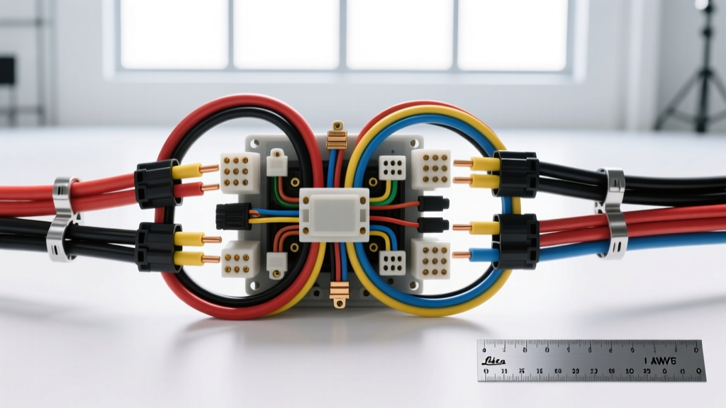
Beyond the Basics: Why Standard Wire Gauges Size Charts Fail in Vehicles
When consulting a standard wire gauges size chart, most automotive hobbyists and even some professional technicians make a critical error: they assume the American Wire Gauge (AWG) system operates identically across all environments. A generic electrical chart based on National Electrical Code (NEC) standards for residential wiring is fundamentally dangerous when applied to a vehicle. Automotive electrical systems operate in a hostile environment characterized by extreme temperature fluctuations, constant vibration, and exposure to corrosive chemicals like oil, coolant, and road salt.
Furthermore, a 12-volt automotive system requires significantly thicker conductors than a 120-volt household system to deliver the same wattage. Because current (Amperage) is the primary driver of resistive heating in a conductor, the low-voltage, high-amperage nature of automotive circuits demands a specialized approach to wire sizing. This advanced guide transcends basic charts, integrating Society of Automotive Engineers (SAE) standards, temperature derating mathematics, and real-world OEM connector specifications to provide a definitive reference for high-performance and restomod wiring.
SAE J1128 vs. Standard AWG: The Insulation Difference
The physical copper diameter of an AWG wire is standardized, but the insulation thickness and thermal rating are not. According to the SAE J1128 Standard for Low Tension Primary Cable, automotive wire must utilize specific insulation compounds designed to withstand under-hood abuse. Standard PVC (Polyvinyl Chloride) wire found in hardware stores begins to melt and degrade at temperatures above 80°C (176°F). In an engine bay where ambient temperatures routinely exceed 120°C near exhaust manifolds, PVC insulation will fail, leading to short circuits and electrical fires.
Modern OEMs specify Cross-Linked Polyethylene (XLPE) insulation. You will typically encounter three SAE J1128 variants:
- TXL (Thin Wall): Rated for 125°C. Used in general chassis and cabin wiring where space and weight are at a premium.
- GXL (General Purpose): Rated for 125°C. The standard for most modern engine bay harnesses. Offers a balance of flexibility and thermal resistance.
- SXL (Special Purpose): Rated for 125°C to 150°C. Features the thickest insulation wall, used in extreme heat zones near turbochargers, exhaust gas recirculation (EGR) systems, and high-performance engine management sensors.
Advanced Automotive Wire Gauges Size Chart (Engine Bay Derated)
The following wire gauges size chart incorporates temperature derating for engine bay applications (assuming an ambient under-hood temperature of 125°C). Standard charts often list 10 AWG as capable of 30 Amps; however, under SAE J1128 high-temperature conditions, that same 10 AWG wire must be derated to prevent insulation meltdown and excessive voltage drop.
| AWG Size | Metric (mm²) | Max Amps (Cabin 40°C) | Max Amps (Engine Bay 125°C) | Typical Automotive Application | Recommended Connector Type |
|---|---|---|---|---|---|
| 18 AWG | 0.8 mm² | 16 A | 10 A | O2 Sensors, MAF, CAN Bus, ECU Signals | Molex MX150, Delphi Weather-Pack |
| 16 AWG | 1.3 mm² | 22 A | 14 A | Injectors, Ignition Coils, Lighting Relays | TE Automotive DT, Sumitomo |
| 14 AWG | 2.0 mm² | 32 A | 20 A | Fuel Pumps, High-Current Solenoids, Horns | Delphi Weather-Pack, Metri-Pack |
| 12 AWG | 3.0 mm² | 41 A | 25 A | ECU Power/Ground, Cooling Fans, Power Windows | Metri-Pack 280, Ring Terminals |
| 10 AWG | 5.0 mm² | 55 A | 35 A | High-Amp Accessories, Winch Controls, Amplifiers | Anderson Powerpole, Heavy Ring |
| 8 AWG | 8.0 mm² | 73 A | 45 A | Alternator Output (Stock), Starter Solenoid | M8 Ring Terminal (Torqued to 18 Nm) |
| 4 AWG | 20.0 mm² | 125 A | 80 A | Upgraded Alternator, Battery Relocation, EV 12V | M10 Ring Terminal (Torqued to 35 Nm) |
| 1/0 AWG | 50.0 mm² | 170 A | 120 A | Main Battery Cables, High-Current EV DC-DC | Heavy Duty Copper Lug (Crimped) |
Temperature Derating Multipliers
If you are routing wire through a firewall or near exhaust components where temperatures exceed the 125°C baseline, you must apply a derating multiplier to the 'Engine Bay' ampacity column above. For 150°C ambient zones, multiply the ampacity by 0.71. For 200°C zones (requiring specialized Teflon/PTFE or fiberglass braided wire), multiply by 0.43.
Voltage Drop Calculations for EFI and EV Systems
Selecting the correct gauge is not just about preventing the wire from melting; it is about maintaining voltage at the component. Electronic Fuel Injection (EFI) systems and modern EV battery management systems (BMS) are highly sensitive to voltage drop. A fuel pump that receives 11.5V instead of 13.8V will experience a drastic reduction in flow rate and pressure, leading to a lean condition and catastrophic engine failure under load.
To calculate voltage drop, use the formula: V = I × R × 2 × L
- V = Voltage Drop
- I = Current in Amps
- R = Resistance per foot of the specific AWG (e.g., 12 AWG is 0.001588 ohms/ft)
- 2 = Multiplier for the complete circuit (positive and negative paths)
- L = Length of the wire run in feet
Real-World Scenario: You are wiring a 20-Amp aftermarket fuel pump located 12 feet from the battery. Using 14 AWG wire (0.002525 ohms/ft).
V = 20 × 0.002525 × 2 × 12 = 1.21 Volts Drop.
This leaves only 12.59V at the pump. Upgrading to 10 AWG (0.0009989 ohms/ft) reduces the drop to 0.47 Volts, ensuring optimal fuel pressure. Consult the Painless Performance Wiring Technical Manuals for comprehensive circuit length charts and relay placement strategies to minimize run lengths.
OEM Color Codes and Signal Sensitivity
While wire gauge dictates current capacity, wire color and shielding dictate signal integrity. When building custom harnesses, adhering to OEM-style color coding prevents disastrous diagnostic errors later. Standard SAE color codes include Black (BK) for ground, Red (RD) for battery positive, and White (WT) for data/sensor returns.
However, advanced engine management requires specific attention to shielding. Low-voltage analog signals, such as those from a Mass Air Flow (MAF) sensor or wideband O2 sensor, operate in the millivolt range. Running these 18 AWG or 20 AWG signal wires parallel to high-current 12 AWG ignition coil wires will induce Electromagnetic Interference (EMI). Always use shielded twisted-pair (STP) cable for crankshaft/camshaft position sensors and CAN bus networks. The shield drain wire must be grounded at the ECU end only to prevent ground loops.
Real-World Failure Modes and Troubleshooting
The 'Upgraded' Alternator Bottleneck
A common failure mode in restomods and high-audio vehicles is upgrading to a 200-Amp alternator but retaining the factory 8 AWG or 6 AWG charge wire. When the audio system demands 150 Amps, the factory wire acts as a massive resistor. The alternator's internal voltage regulator senses the voltage at its output stud, not at the battery. It will push voltage dangerously high (sometimes exceeding 16V) to force current through the undersized wire, frying the vehicle's ECU and sensitive electronics. Always match the charge wire to the alternator's maximum output using the derated chart above (e.g., 1/0 AWG for a 200A+ alternator).
Chassis Ground vs. Dedicated Return Paths
Historically, vehicles used the steel chassis as the ground return path to save copper weight. Modern vehicles with unibody construction, extensive use of aluminum subframes, and rubber-isolated powertrains cannot rely on chassis grounding for high-current or sensitive ECU circuits. Rubber engine mounts isolate the engine block, forcing current through small braided ground straps that quickly corrode and fail.
For aftermarket EFI, dedicated ground rings must be established. Use a minimum of 12 AWG wire to ground the ECU, fuel pump relay, and ignition modules directly to the battery negative terminal or a centralized, clean copper busbar bolted to bare metal. When terminating ground lugs, always use a star washer or sand the paint down to bare metal, and apply dielectric grease over the terminal to prevent galvanic corrosion.
High-Voltage EV Cabling: Metric vs. AWG Crossover
As automotive electrical systems transition to high-voltage Electric Vehicle (EV) architectures, the traditional wire gauges size chart requires a metric translation. EV battery packs and inverters operate between 400V and 800V, utilizing shielded, bright orange high-voltage cables. These are sized in square millimeters (mm²) rather than AWG.
For technicians bridging the gap between legacy AWG tools and modern metric EV cabling, the closest crossovers are: 16 mm² (approx. 5 AWG), 25 mm² (approx. 3 AWG), 35 mm² (approx. 2 AWG), 50 mm² (approx. 1/0 AWG), and 70 mm² (approx. 2/0 AWG). Unlike standard 12V wiring, EV high-voltage cables require specialized shielded crimp terminations and strict adherence to manufacturer torque specs on inverter lugs to prevent high-frequency arcing and thermal runaway.