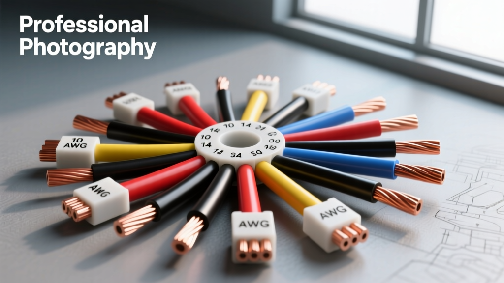
The Lifeblood of Your Vehicle: Understanding Wire Gauges
Whether you are installing a high-output alternator, upgrading to LED lighting, or troubleshooting a parasitic draw, understanding automotive wire gauges is the most critical fundamental skill you can develop. The electrical system in a modern vehicle is a complex network of sensors, modules, and high-current loads. Using the incorrect wire size doesn't just lead to dim headlights or slow power windows; it creates severe fire hazards and can destroy expensive Engine Control Units (ECUs). In this beginner-friendly guide, we will decode the American Wire Gauge (AWG) system, explore SAE automotive standards, and provide actionable wiring configurations for common 12V applications.
What is AWG? The American Wire Gauge Standard
The American Wire Gauge (AWG) is the standardized wire sizing system used predominantly in North America. It measures the cross-sectional area of a solid or stranded conductor, which directly determines its electrical resistance and current-carrying capacity (ampacity). For automotive applications, we almost exclusively use stranded copper wire because solid core wire will quickly fracture and break under the constant vibration of a running vehicle.
Why Smaller Numbers Mean Thicker Wires
The most common point of confusion for beginners is the inverse relationship between the gauge number and the wire thickness. A 10 AWG wire is significantly thicker than a 16 AWG wire. This numbering system originates from the historical manufacturing process of wire drawing. To make a wire thinner, it had to be pulled through a series of progressively smaller drawing dies. Therefore, a wire that was drawn through 10 dies (10 AWG) is thicker than a wire drawn through 16 dies (16 AWG). When selecting wire, always remember: lower gauge number equals thicker wire, lower resistance, and higher current capacity.
Automotive Wire Gauge Ampacity Chart
Ampacity refers to the maximum amount of electrical current a conductor can safely carry before its insulation begins to melt or degrade. The chart below outlines standard chassis wiring ampacities for stranded copper wire in a 12V automotive environment. Note that these ratings assume single wires in free air at standard under-hood temperatures. Bundling multiple wires together inside a split-loom conduit reduces heat dissipation and requires you to de-rate the ampacity by 15% to 20%.
| AWG Size | Strand Count | Max Amps (Chassis) | Typical Automotive Application |
|---|---|---|---|
| 8 AWG | 133 | 40A - 50A | Battery to alternator (short runs), high-power audio amplifiers, winch solenoids |
| 10 AWG | 105 | 30A | Headlight power feeds, fuel pump relays, cooling fan primary circuits |
| 12 AWG | 65 | 20A | Accessory circuits, cigarette lighter sockets, power seat motors |
| 14 AWG | 41 | 15A | Tail lights, horn relays, windshield wiper motors |
| 16 AWG | 26 | 10A | ECU sensor feeds, dashboard illumination, door lock actuators |
| 18 AWG | 16 | 5A - 7A | Low current signals, CAN bus lines, injector pulse triggers |
For a comprehensive look at exact circular mil measurements and voltage drop metrics, refer to the Waytek Wire Gauge and Ampacity Charts, which provide excellent baseline data for aftermarket installations.
SAE vs. AWG: Understanding Automotive Insulation Standards
While AWG defines the copper conductor, it says nothing about the insulation. Household wire (like THHN) uses PVC insulation that becomes brittle and melts at relatively low temperatures. Automotive environments demand insulation that can withstand under-hood temperatures exceeding 125°C (257°F), exposure to oil, brake fluid, and constant abrasion. This is where the SAE International J1128 Standard comes into play.
GXL vs. TXL vs. SXL Wire Types
When purchasing automotive primary wire, you will encounter three main cross-linked polyethylene (XLPE) insulation types:
- GXL (General Cross-Linked): The standard for most aftermarket and OEM automotive wiring. It offers an excellent balance of thin insulation, high heat resistance (up to 125°C), and flexibility.
- TXL (Thin Cross-Linked): Features even thinner insulation than GXL, saving weight and allowing more wires to fit into tight OEM connector cavities like the Delphi Metri-Pack 280 series. Rated for 125°C.
- SXL (Special Cross-Linked): Thicker insulation designed for heavy-duty commercial trucks and high-vibration environments where physical abrasion is a major concern.
Real-World Application: Wiring a Headlight Relay Harness
To put these wire gauges into practice, let us look at upgrading a classic vehicle's dim factory headlights using a standard Bosch-style 5-pin relay (Pins 30, 87, 87a, 85, and 86). Upgrading to 10 AWG wire ensures maximum voltage reaches the halogen or LED bulbs.
- Pin 30 (Power In): Run 10 AWG Red wire directly from the positive battery terminal to Pin 30. Install an inline 30A MAXI fuse within 18 inches of the battery to protect the main feed.
- Pin 87 (Power Out): Run 10 AWG Red wire from Pin 87 to the headlight connector. Use a weather-sealed H4 ceramic pigtail to prevent melting at the bulb housing.
- Pin 85 (Ground): Run 14 AWG Black wire from Pin 85 to a clean, bare-metal chassis ground. Use a ring terminal with a star washer to bite through paint and rust.
- Pin 86 (Trigger): Run 16 AWG Yellow wire from Pin 86 to the vehicle's original headlight switch positive output. This low-current signal only needs to energize the relay's internal electromagnet, so 16 AWG is perfectly sufficient and easy to route through the firewall.
Always terminate these connections using adhesive-lined marine-grade heat shrink crimp terminals. The internal adhesive melts during the heating process, sealing out moisture and preventing the green corrosion that plagues amateur wiring jobs.
Voltage Drop: The Hidden Enemy of 12V Systems
Beginners often select a wire gauge based solely on its ampacity, ignoring the length of the wire run. In a 12V automotive system, even a small resistance over a long distance causes a significant voltage drop. If your fuel pump requires 12V but only receives 10.5V due to undersized wire, it will run slower, overheat, and prematurely fail.
Voltage drop is calculated using the formula: VD = (2 x K x I x L) / CM, where K is the resistivity of copper (approx. 12.9), I is current in amps, L is the one-way length in feet, and CM is the circular mil area of the wire. A 16 AWG wire carrying 10 amps over a 20-foot round trip will drop nearly 2 volts. To prevent this, always use a Voltage Drop Calculator before finalizing long wire runs for fuel pumps, winches, or rear-mounted auxiliary lighting. As a general rule, aim for a maximum voltage drop of 3% (0.36V) on critical circuits.
Common Beginner Mistakes to Avoid
Even with the correct wire gauge, poor execution will ruin an electrical build. Avoid these common pitfalls:
- Using Solid Core Wire: Never use household Romex or solid copper wire in a vehicle. The engine's harmonic vibrations will cause solid wire to work-harden and snap inside the insulation.
- Soldering Instead of Crimping: While soldering seems secure, it creates a rigid point on a flexible stranded wire. Under vibration, the wire will fracture exactly where the solder ends. Always use a ratcheting crimping tool designed for the specific terminal type (e.g., F-crimp or double-crimp barrels).
- Ignoring Wire Color Standards: While OEM wiring varies wildly, stick to standard aftermarket color codes for custom builds: Red for constant 12V, Black for ground, Yellow for switched 12V, and Blue/Green for signal or trigger wires. This saves hours of troubleshooting later.
Conclusion
Mastering automotive wire gauges is about more than just memorizing a chart. It requires understanding the relationship between current, resistance, temperature, and physical environment. By selecting the proper AWG size, utilizing SAE J1128 rated cross-linked insulation, and executing professional-grade crimped connections, you will build a vehicle electrical system that is safe, reliable, and capable of handling modern accessory loads for years to come.